User Guide
MP2672 Evaluation Kit (EVKT-MP2672)
MP2672 Evaluation Kit User Guide rev 1.0 MonolithicPower.com 6
10/15/2019 MPS Proprietary Information. Patent Protected. Unauthorized Photocopy and Duplication Prohibited.
© 2019 MPS. All Rights Reserved.
Section 3. Evaluation Kit Test Set-up
3.1 Hardware Setup
The hardware must be properly configured prior to use. Follow the instructions below to set up the EVB:
1. Locate the proper wires to connect the EVB to the EVKT-USBI2C-02 communication interface.
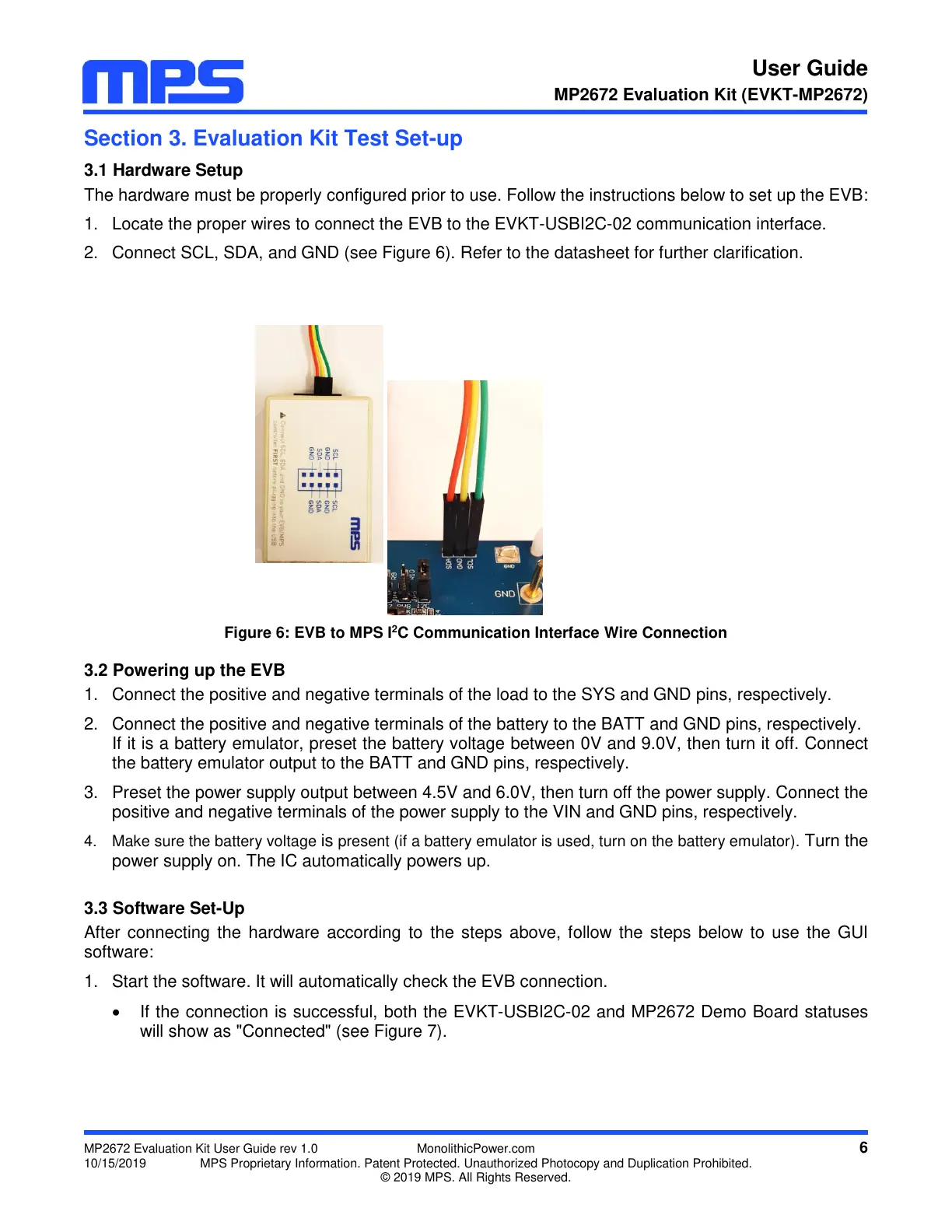
2. Connect SCL, SDA, and GND (see Figure 6). Refer to the datasheet for further clarification.
Figure 6: EVB to MPS I
2
C Communication Interface Wire Connection
3.2 Powering up the EVB
1. Connect the positive and negative terminals of the load to the SYS and GND pins, respectively.
2. Connect the positive and negative terminals of the battery to the BATT and GND pins, respectively.
If it is a battery emulator, preset the battery voltage between 0V and 9.0V, then turn it off. Connect
the battery emulator output to the BATT and GND pins, respectively.
3. Preset the power supply output between 4.5V and 6.0V, then turn off the power supply. Connect the
positive and negative terminals of the power supply to the VIN and GND pins, respectively.
4. Make sure the battery voltage is present (if a battery emulator is used, turn on the battery emulator). Turn the
power supply on. The IC automatically powers up.
3.3 Software Set-Up
After connecting the hardware according to the steps above, follow the steps below to use the GUI
software:
1. Start the software. It will automatically check the EVB connection.
If the connection is successful, both the EVKT-USBI2C-02 and MP2672 Demo Board statuses
will show as "Connected" (see Figure 7).