4 Commissioning
Maschinenfabrik Reinhausen GmbH 202032 5993419/02 ENVACUTAP
®
VMS
®
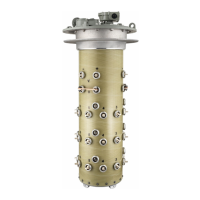
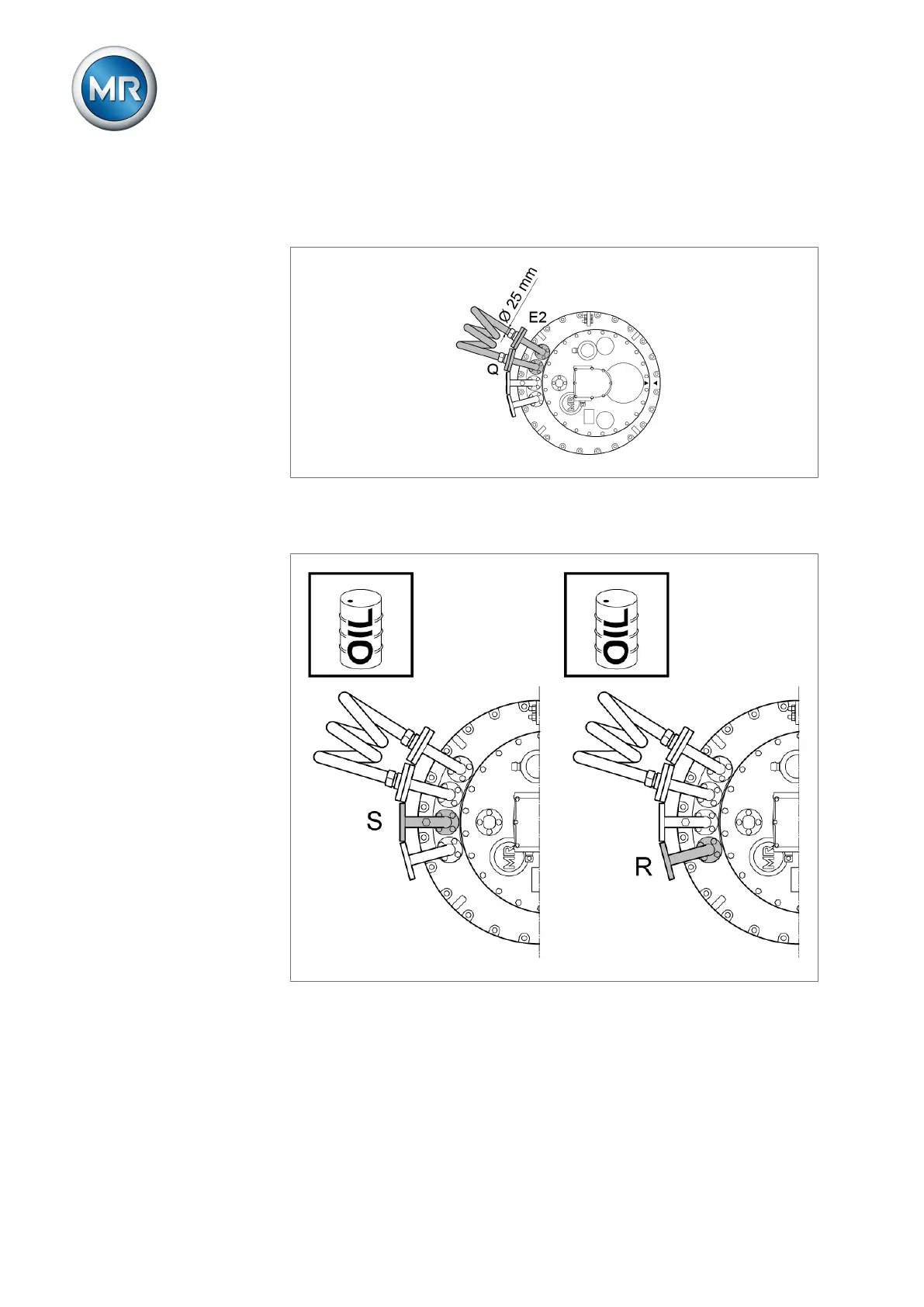
2. Establish a connecting lead between pipe connection E2 and one of the
pipe connections R, S or Q to ensure equal pressure in the oil compart-
ment and transformer during evacuation.
Figure17: Connecting lead between E2 and Q
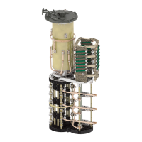
3. Fill on-load tap-changer with new insulating fluid using one of the two free
pipe connections of the on-load tap-changer head.
Figure18: Pipe connections S and R
4. Take a sample of insulating fluid from the oil compartment.
5. Record the temperature of the sample immediately after the sample is
taken.
6. Determine dielectric strength and water content at an insulating fluid tem-
perature of 20°C ± 5°C. The dielectric strength and water content must
comply with the limit values specified in the technical data.