Test Applications
(Figure 8)
V V
735Ω
While the tool is in DC voltage mode, contact the probe tip to a positive circuit,
the red LED will light. If the beep is turned on, a high pitched tone will sound.
If contact the probe tip to a negative circuit, the green LED will light. If the beep
is turned on, a low pitched tone will sound.
If contact the probe tip to an open circuit, neither of the LED will light (Figure 6).
Voltage & Polarity Testing:
While the tool is in resistance mode,
using the probe tip with chassis ground
or the auxiliary ground lead, continuity
can be tested on wires and components
attached or disconnected from the
vehicle's electrical system.
When the probe tip is contacting a good
grounding, the LCD will indicate 0.0Ω
and green LED will be ON. If the tone
feature is turned on, a low pitched tone
will sound (Figure 7).
Continuity Testing:
(Figure 5)
(Figure 6)
Press and
Hold to
Change!
V V
V
V
0.0
V
V
12.0
(Figure 7)
V V
0.0Ω
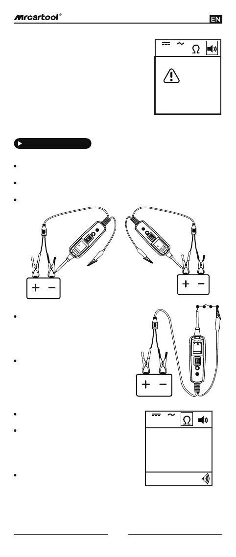
4
required, for example, to test a circuit for a long
period of time, where the audio may become
annoying.
In other cases, the LCD only indicates
the resistance value (Figure 8).
There is also another way to prove
continuity of connections to ground or
battery, powering up the connec- tion
using the power switch . If the circuit
breaker trips, it indicates that it has a
good solid low resistance connection.
Note: You can use the probe tip to pierce
the plastic insulation on a wire. This
means that you can test the circuit
without disconnecting anything.