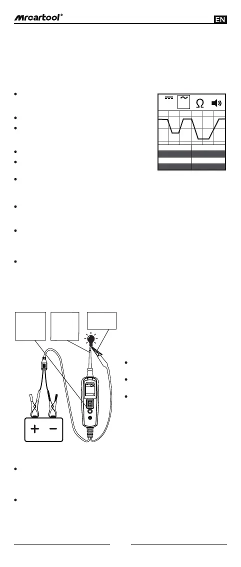
(Figure 9)
V V
Max
Min Duty
Freq
12.3V 0.6Hz
49%
0.3V
Set the tool in AC voltage mode, using the probe
tip with chassis ground or the auxiliary ground
lead.
Connect vacuum pump to MAP sensor.
Contact the probe tip to the MAP sensor positive
terminal and observe the LCD readings which
should be a sine wave in normal condition.
Apply vacuum.
Release vacuum and observe the LCD readings
(Figure 9).
If the LCD readings are abnormal, there is a
problem with this sensor.
Once you extract a DTC from the vehicle and realize that troubleshooting begins
with some kind of sensor circuit, there is a quick test you can perform to verify the
code, testing your sensor is easy while using the tool.
For example, if there is a problem with the MAP sensor circuit, then follow the
procedure involved with testing the sensor:
Signal Circuit Testing:
While the tool is in DC voltage mode, by using the probe tip in connection with
the auxiliary ground lead, components can be activated right in your hand,
thereby testing their functions.
Connect the auxiliary ground lead to the negative terminal or ground side of
the component being tested. Then contact the probe tip to the positive
terminal of the component, the green LED would light on, which indicates
continuity through the component.
Please observe the green LED. If the green LED goes off and the red LED goes
on, then quickly press and release the power switch forward. You may proceed
with further activation. As the power switch is rocked forward, power will flow
from the positive lead on the battery into the probe tip, through the tip into the
positive terminal of the component, into and out of the component, through the
auxiliary ground lead and back into the tool, and then back to the vehicle
battery ground (Figure 10).
Activating Components in the Hand:
While the tool is in DC voltage mode, clip the auxiliary ground lead to the trailer
ground. Then probe the contacts at the jack and apply voltage to the probe tip,
which allows you to check the function and orientation of the connector and
trailer lights (Figure 11).
If the circuit breaker tripped, that contact is likely a grounded. Reset the circuit
breaker by letting it cool down for 15 seconds and depressing the reset button
until it clicks into place.
Testing Trailer Lights and Connections:
(Figure 10)
V V
0.0Ω
Contact the
tip to the
positive
terminal of
the bulb
Connect the
negative
auxiliary clip
Press the
power switch
forward to
activate the
bulb
5
The contact you are probing is a
direct ground or negative voltage.
The component you are testing is
short-circuited.
The component is of a high current
component (i.e., starter motor).
If the green LED goes off at that instant
or if the circuit breaker tripped, that
means the tool has been overloaded.
This could happen for the following
reasons:
If the circuit breaker is tripped , reset it
by waiting for it to cool down 15 sec
and the depressing the reset button.