Outdoor Unit Disassembly 31
PCB board 3
Procedure Illustration
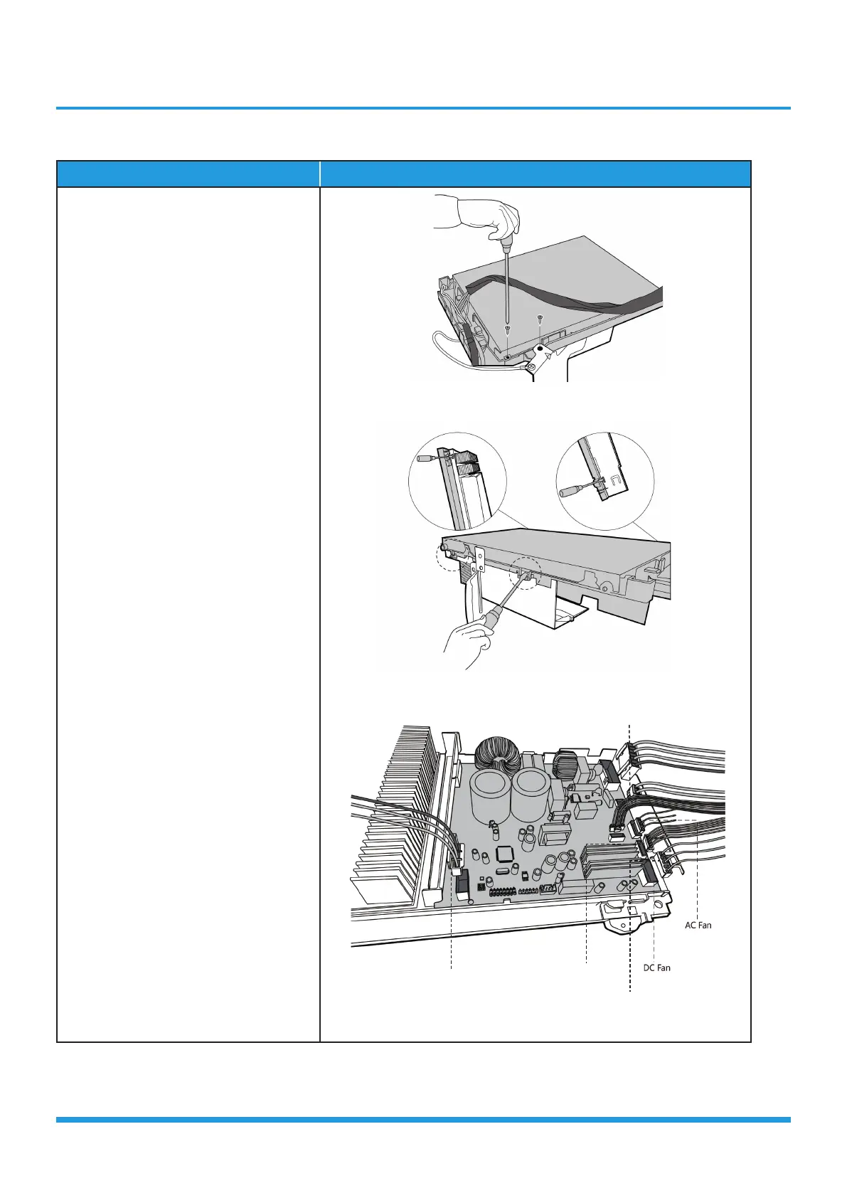
1) Remove the screws of the top
cover. (2 screws) (see CJ_Multi-
PCB_003-1).
2) Unfix the hooks and then open the
electronic control box cover (4 hooks)
(see CJ_Multi-PCB_003-2).
3) Disconnect the connector for fan
motor from the electronic control
board (see CJ_Multi-PCB_003-3).
4) Remove the connector for the
compressor (see CJ_Multi-
PCB_003-3).
5) Pull out the two blue wires
connected with the four way valve
(CJ_Multi-PCB_003-3).
6) Pull out connectors of the condenser
coil temp. sensor(T3),outdoor
ambient temp. sensor(T4) and
discharge temp. sensor(TP) (CJ_
Multi-PCB_003-3).
7) Disconnect the electronic expansion
valve wire (CJ_Multi-PCB_003-3).
8) Then remove the electronic control
board.
CJ_Multi-PCB_003-1
CJ_Multi-PCB_003-2
CJ_Multi-PCB_003-3
Note: This section is for reference only. Actual unit appearance may vary.
Compressor
T3, T4, TP
Electronic Expansion Valve
4-Way Valve