GLOSSARY (continued)
ZONE SETTING: This is the main entry to the PROGRAMMING SCREEN for the
INTERSECTOR.
PROGRAMMING SCREEN: This is the area where the installer can setup detection zones,
Offset Angle, and track vehicle progress. This screen consists of three main parts: The
TARGET SETUP TABLE, VEHICLE TABLE, and DATA DISPLAY.
SET ZONE DATA: This function stores zone data to hard memory. When any data is
changed on the PROGRAMMING SCREEN, it will only be stored when this is selected.
TARGET SETUP TABLE: This section of the PROGRAMMING SCREEN is where all setup
data will be entered to be installed to the INTERSECTOR. The Table consists of several
data values:
• ZONE: Zone is the term used to describe the area where the vehicle will be
detected. In some cases this is known as the “loop”. Up to 8 separate zones
can be created.
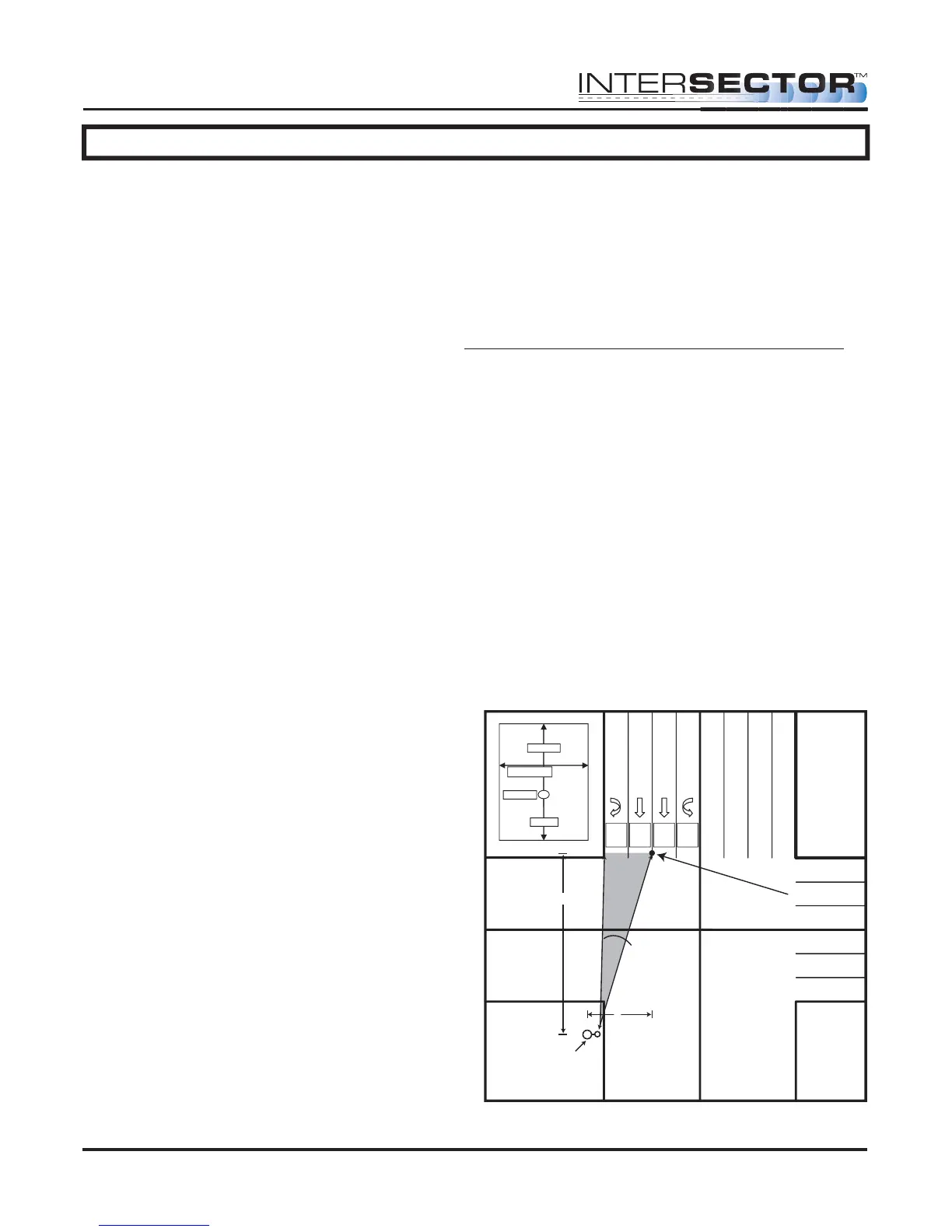
• X: X is the first coordinate used to determine the location of a zone. The
X coordinate is the horizontal dimension and represents the distance from the
sensor to the center of the zone in the X axis (Diagram 1).
• Y: Y is the second coordinate used to determine the location of a zone. The
Y coordinate is the vertical dimension and represents the distance from the
sensor to the center of the stop bar zone (Diagram 1).
• Y Front: This value extends the zone in front of the original point (closer to
the intersection).
• Y Behind: This value is the depth of the zone behind the original point
(farther from the intersection).
• Width of Zone: This is the width of
the zone in relation to its center.
• DELAY TIME: Time that the detector
will wait before allowing the output
to be recognized.
• EXTENSION TIME: Time that the
output will extend after a vehicle
leaves the zone.
• OPTO OUTPUT: This value indicates
the output for the controller input
(rack). A setting of 0 indicates the
output for this zone is currently
disabled.
INTERSECTOR
Microwave Motion and
Presence Sensor Installation Instructions
MS Sedco INTERSECTOR Installation Instructions Page 3 INTERSECTOR-1.9Uv092717
Center of
Stop Bar Zone
Offset Angle
Zone 4
Opto 4
Zone 3
Opto 3
Zone 2
Opto 2
Zone 1
Opto 1
X
Y
Corner Pole /
Sensor Location
NOTE: Unit mounts on
side of pole.
Zone 1
Width of lane
X and Y
Y front
Y behind