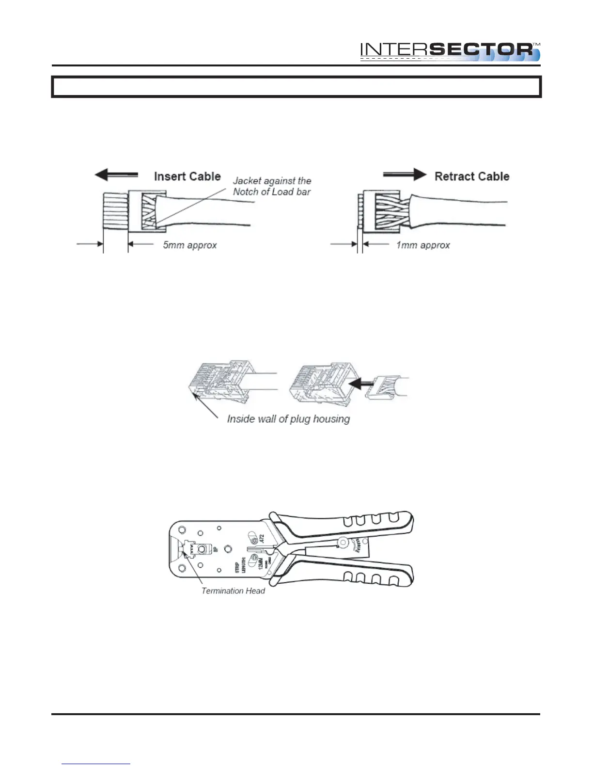
Figure 4 Figure 5
INTERSECTOR Microwave Motion and
Presence Sensor Installation Instructions
MS Sedco INTERSECTOR Installation Instructions Page 10 INTERSECTOR-1.9Uv092717
IMPORTANT – No wires should be exposed when the plug is fully in place.
Figure 7
INSTALLATION (continued)
After inserting the wires into the appropriate positions of the load bar, slide the cable to
a point where the cable jacket hits the notch of the load bar. Trim the remaining wire
ends to approximately 5mm length as shown in Figure 4. Retract the cable, leaving
approximately 1mm of wire tips as shown in Figure 5.
Insert the wired load bar into the RJ45 plug all the way until the wire tips are sealed
against the inside wall of the plug housing (Figure 6).
Terminate the cable and the RJ45 plug with a modular plug termination tool similar to
the one shown in Figure 7.
Depress the locking tab of the RJ45 plug and align it with the wide slot of the plug
housing shown in Figure 8 Detail A. Gently pull the cable until the plug is fully seated.
Hold the plug in position and rotate cable fitting until tightened to a torque of 3.4 Nm (30
lb-in) as shown in Figure 8 Detail B.
Figure 6