INSTALLATION (continued)
It is necessary to prepare the cable and insert it through the housing prior to attaching
the load bar and Ethernet connector (RJ45 plug).
NOTE: Cat.5e direct burial shielded cable is recommended to keep
Electromagnetic Interference, or (EMI), from effecting the ability of the cable to
transmit data. EMI can pass through the cable, corrupting your data and shutting
down communication. The Shielding in the wire helps to prevent this energy from
getting through and causing adverse effects to the TC-CK1-SBE communication
data.
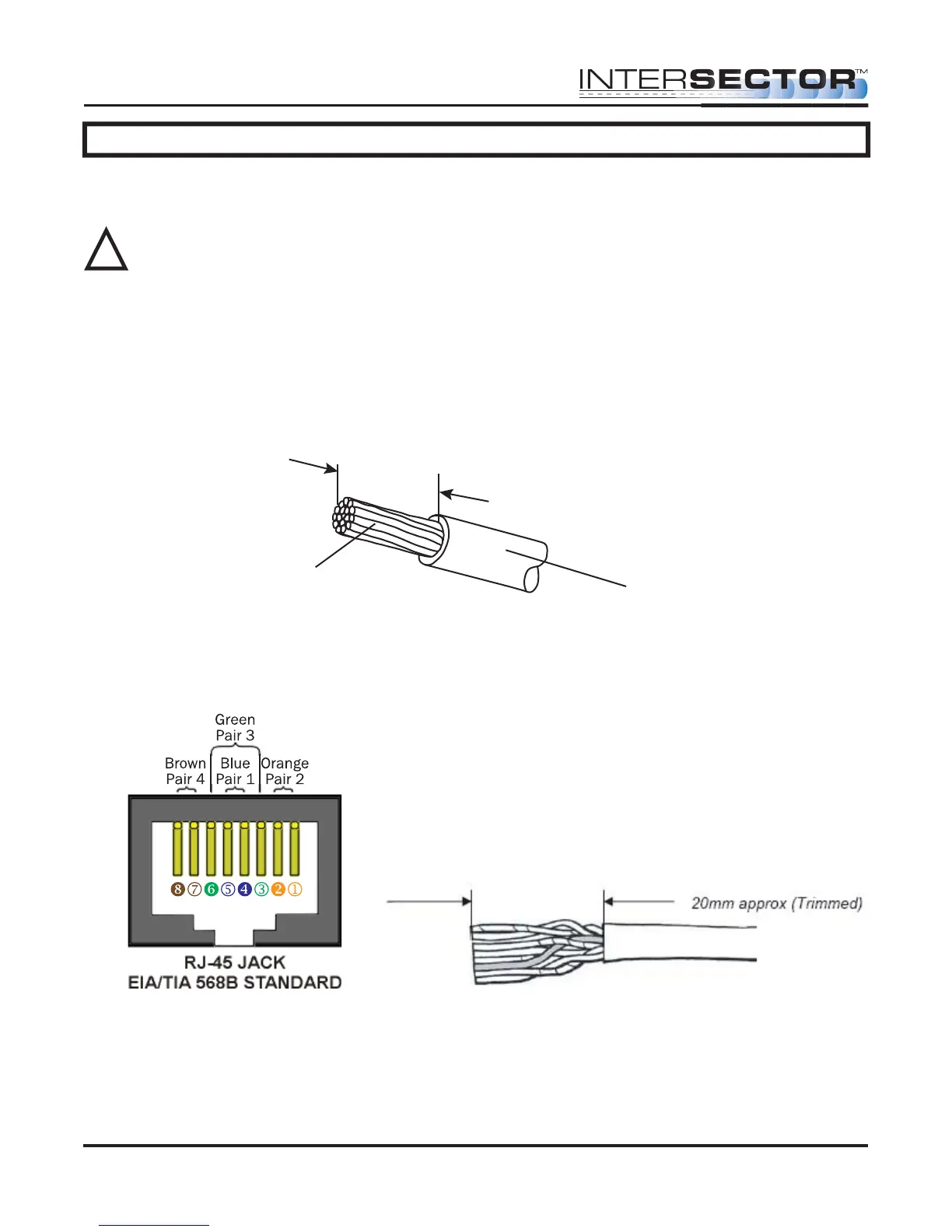
CABLE PREPARATION: Using an 8 conductor, 24 AWG per conductor solid or stranded
cable, the cable jacket should be stripped as shown in Figure 1 and then inserted
through the cable fitting and the plug housing assembly.
Conductors should be untwisted and aligned side by side for a T568B connector. Refer
to Figure 2 to determine the proper alignment of the cable conductors.
The conductor wire ends should be trimmed as shown in Figure 3. Untwist as little of
the cable as possible. Be careful not to remove the insulation of individual conductors!
Figure 2
Figure 3
Figure 1
Strip 25mm length approx.
Jacket
Conductor
INTERSECTOR Microwave Motion and
Presence Sensor Installation Instructions
MS Sedco INTERSECTOR Installation Instructions Page 9 INTERSECTOR-1.9Uv092717
!