INSTALLATION (continued)
Distance ............Max # ................Angle Mounting........................ Height
to Stop Bar Lanes (˚) (ft.)
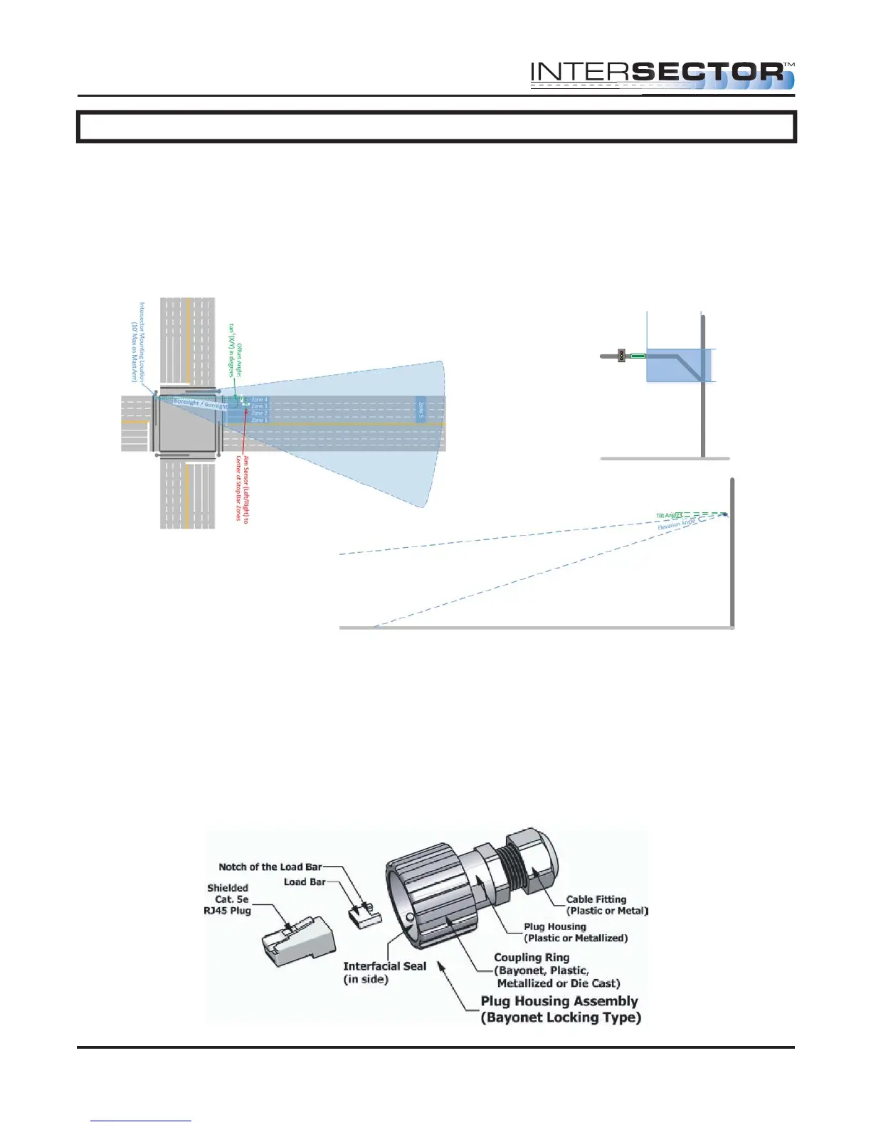
60-80 feet .................... 2 ...............................-6 degrees ..................................... 16 feet
80-100 feet .................. 3 ...............................-6 degrees ..................................... 17 feet
100-120 feet ................ 4 ...............................-4 degrees ..................................... 18 feet
120-160 feet ................ 4 ...............................-2 degrees ..................................... 19 feet
Connection of the sensor to the traffic cabinet is accomplished using an Ethernet cable.
The cable is routed through a quick connect assembly that is then connected to the
sensor. The other end of the cable is routed to the traffic cabinet and plugs into the
interface board. The next section will detail the preparation and installation of the
sensor Ethernet cable.
QUICK CONNECT ASSEMBLY INSTRUCTIONS:
The quick connect consists of a shielded Cat. 5e RJ45 Plug, a load bar, and a Plug
Housing Assembly.
INTERSECTOR
Microwave Motion and
Presence Sensor Installation Instructions
MS Sedco INTERSECTOR Installation Instructions Page 8 INTERSECTOR-1.9Uv092717
14'
20'
0'
10'
Intersector
Mounng Area
FIGURE 2: Recommended INTERSECTOR™
Mounting Location Depiction
FIGURE 1: INTERSECTOR™ Installation Example
FIGURE 3: INTERSECTOR™ Tilt and
Elevation Angle