25
Installation
GB
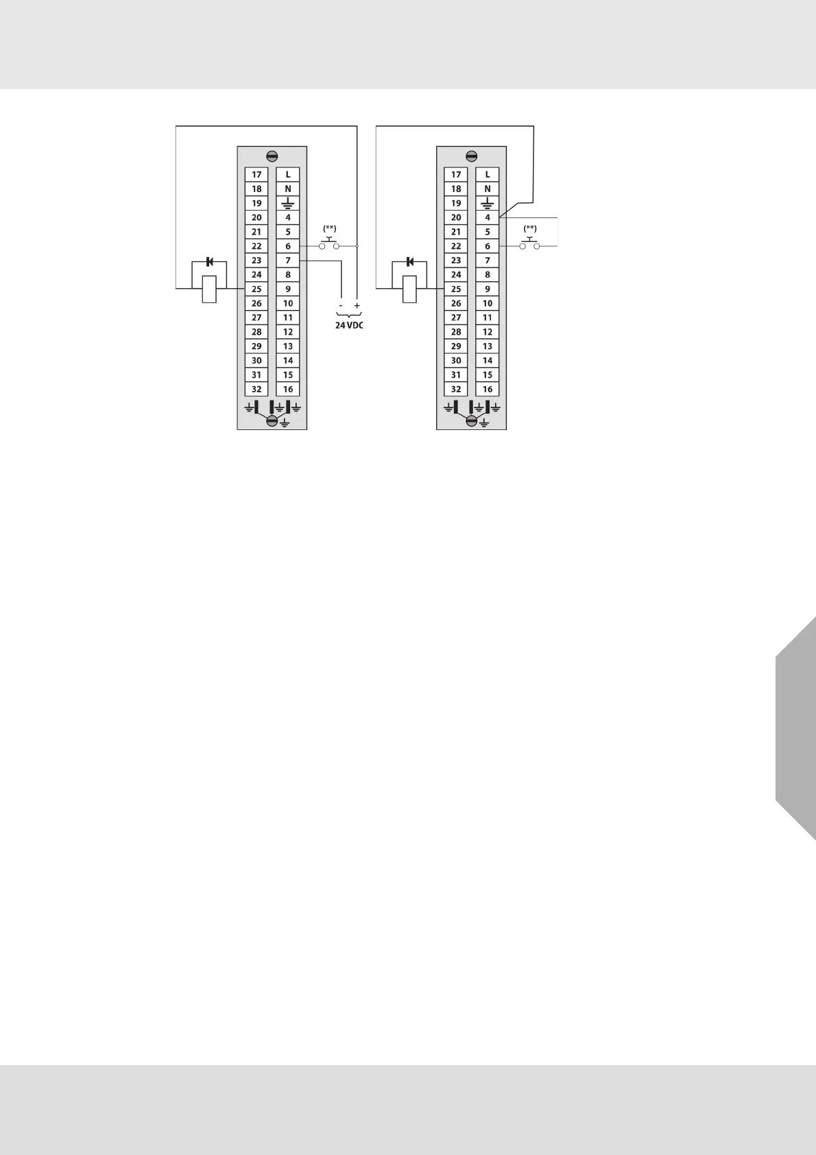
Model 9010/9020 SIL
Fig. 9 „CAUTION“ output connection to external relay and for button for remote acknowledgement and
alarm reset
3.3 Initial System Check after Installation
The entire system must be checked after the initial installation ensuring correct function in accor-
dance with the EN 60079-29-2 and the applicable international, national, industry-specific or
company regulations.
(1) Run initial start-up procedure (See chapter 4.1).
(2) Perform a functional test of connected detectors applying zero and test gas with an equiva-
lent gas concentration (in general higher than the preset alarm thresholds).
(3) Check whether the gas value on the display corresponds with a concentration of the test gas.
Detectors providing output signal outside of their accuracy interval must be recalibrated or
replaced.
(4) Check the CAUTION, WARNING and ALARM LEDs and outputs activation as well as the
HORN relay activation individually for each alarm level during the functional test.
(5) Check the FAILURE LED and relay activation in case of detector/transmitter failure simula-
tion.
(6) Record test results in the protocol according to local regulations.
Maximum relay current at 24 VDC = 30 mA Maximum relay current at 24 VDC = 30 mA
(**) External push button for horn deactivation and reset