43
Settings Parameters
GB
Model 9010/9020 SIL
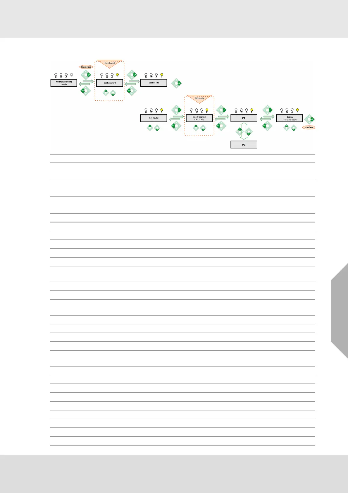
5.8 Access Code 53 - Default Settings
Default Factory Configuration
Step Function
P1
Load Factory Default Settings
"def" symbol is displayed if menu is activated. Press ENTER to load factory default values.
P2
Load User Default Settings
"defC" symbol is displayed if menu is activated. Press ENTER to load user default values.
Access Code Description Default Value
Overrange Function (EEEE) A (Enabled)
- Positive Dead Band Zero Value +2 %
- Negative Dead Band Zero Value -2 %
- Horn Output Status dE (Normally not energized),
AC1 P2 Span Calibration Gas Concentration 50 % FS
AC1 P6
Time Interval Between Calibrations Notifica-
tion
0 (Disabled)
AC1 P8 Detector Sensitivity Reduction Warning nA (Disabled)
AC2 P1 Time out function A (Enabled)
AC2 P2
Analog Output signal (during a calibration
procedure)
2 mA
AC2 P3 Alarm Inhibited A (Alarms active)
AC2 P4 Undervoltage of External 24 VDC nA (Disabled)
AC2 P5 Undervoltage of External 115/230 VAC A (Enabled)
AC4 P1 Detector Supply Current Setting 310 mA
AC4 P2
Minimum 4-20 mA Transmitter Supply
Current
25 mA
AC4 P3 Maximum Negative Drift -3%
AC4 P4 Measuring Units LEL
AC4 P5 Offset Value 0
AC4 P6 Full Scale Value 100
AC4 P7/ P11/ P15 Alarm Direction C / W / A - U (Rising alarm)
AC4 P7/ P11/ P15 Alarm Thresholds Values C=15, W=15, A=30
AC4 P8/ P12/ P16 Digital Outputs Status C / W / A - E (Energized)
AC4 P9/ P13/ P17 Alarm Reset mode C=1A, W=1A, A=1M
AC4 P10/ P14/ P18 Alarm Mode norM (no STEL or TWA)