Do you have a question about the MSA ALTAIR 4XR and is the answer not in the manual?
Details the intended applications and purpose of the ALTAIR 4XR Multigas Detector.
Instructions on preventing sensor damage and ensuring accurate readings.
Provides critical safety limitations and precautions for device operation and handling.
Outlines specific conditions for safe operation, including combustible sensor overrange.
Advises on bump test frequency and procedure for verifying sensor functionality.
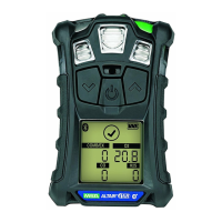
Details the three function buttons and their roles in device operation and setup.
Details battery life indicator, warnings, and device runtime under various conditions.
Provides warnings and instructions for charging the device's battery safely.
Details oxygen monitoring, alarm set points (enriched/deficient), and factors affecting readings.
Explains monitoring of combustible gases, LEL/CH4 readings, and lock alarm states.
Details the shutdown process and necessary actions when the battery is critically low.
Describes the warning given when a sensor is nearing its end of life.
Describes actions to take when the battery warning alarm activates to prevent injury or death.
Explains the display indication for sensors that cannot be calibrated due to end of life.
Lists toxic gases monitored and the types of alarms (High, Low, STEL, TWA).
Details the device startup sequence, self-test, and the Fresh Air Setup process.
Details the FAS screen and its purpose for automatic zero calibration.
Explains how to check readings and access options pages in normal operation mode.
Details how to turn individual sensors on or off.
Provides detailed steps for performing a daily bump test to verify device operation.
Describes how to set calibration values, display Cal Due, and set password.
Explains manual and automatic calibration procedures using a flow regulator.
Guides through connecting gas and performing the span calibration procedure.
Explains potential causes and indicators of span calibration failure.
Explains how to switch alarms on/off and adjust alarm set points.
Details the process for performing Fresh Air Setup and Zero Calibration.
Explains how to access and navigate device setup menus, including password entry.
Provides a table of common problems, their descriptions, and recommended reactions.
Detailed steps for safely replacing or adding sensors, including grounding precautions.
Details the default LOW, HIGH, STEL, and TWA alarm set points for each sensor type.
Illustrates the sequence of screens and operations during device power-on.
Flowchart detailing the Fresh Air Setup process from the startup sequence.
Flowchart detailing the steps for performing a bump test on the device.
Flowchart for accessing and navigating various setup options like Sensor, Calibration, and Alarm.
Flowchart detailing the Zero and Span calibration procedures for the device.
Flowchart for setting alarms on/off and adjusting alarm set points for each sensor.
| Ingress Protection | IP68 |
|---|---|
| Data Logging | Yes |
| Wireless Connectivity | Bluetooth |
| Display | LCD |
| Gas Types | LEL, O2, CO, H2S |
| Sensor Type | Electrochemical, Catalytic |
| Operating Humidity Range | 10% to 95% RH (non-condensing) |
| Alarm Type | Audible, Visual, Vibrating |
| Battery Life | 24 hours (typical); Recharge Time: <6 hours |