Do you have a question about the MSA General Monitors FL500 UV/IR and is the answer not in the manual?
Safety precautions and guidelines for correct device operation and installation.
General Monitors accepts no liability for misuse or unauthorized modifications.
Covers defects for two years; sole remedy is repair or replacement.
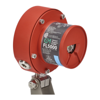
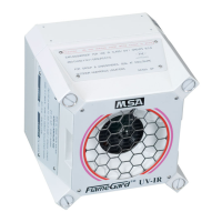
Introduces FL500 UV/IR and FL500-H2 models and their detection principles.
Explains the COPM feature for detecting optical path blockages.
Defines LED indicators for device status and operational modes.
Lists tools needed for installation.
Guidance on selecting suitable installation locations for the device.
Details the device's detection range and angles for various fuels.
Discusses environmental conditions affecting installation and operation.
Instructions and dimensions for mounting the device.
Guidelines and warnings for wiring the device.
Details the 20 terminal connections and their functions.
Explains the configuration options for the Alarm High relay.
Explains the configuration options for the Alarm Low relay.
Describes the standard configuration for the Fault relay.
Instructions for connecting and using an Alarm Reset switch.
Details analog output signals, Modbus, and HART communication.
Specifies maximum cable lengths for interfaces and power supply.
Defines the voltage range and requirements for the power supply.
Instructions for connecting the chassis ground.
Information on compatibility with fire alarm systems and resistors.
Guidelines for terminating cables in nonhazardous areas.
Steps to perform before applying power and the start-up sequence.
Overview of how to change device settings.
Detailed instructions for using the DIP switch for configuration.
Instructions for configuring settings via Modbus or HART.
How to perform a sensitivity check on the device.
Usage instructions for the TL105 Test Lamp.
Instructions for using the Alarm Test feature.
Guidelines for routine maintenance tasks and intervals.
Detailed instructions for cleaning optical components.
Procedures for annual maintenance checks.
A table listing common problems and their corrective actions.
Contact information for repairs and related publications.
Details product model, location, and environmental ratings.
Covers enclosure material, dimensions, weight, and cable entry.
Details supply voltage, current, output signals, and communication specs.
Lists operating/storage temperature and humidity ranges.
| Brand | MSA |
|---|---|
| Model | General Monitors FL500 UV/IR |
| Category | Security Sensors |
| Language | English |