EasyManua.ls Logo

MSA FlameGard Series User Manual

MSA FlameGard Series
34 pages
To Next Page IconTo Next Page
Page #1 background imageLoading...
Page #1 background image
6\Q]U7QbT
6\Q]U 4UdUSd_b
8]bcadRcX^] <P]dP[
»
H2C?:?8
C78B<0=D0;<DBC14 20A45D;;H A4031H 0;; 8=38E83D0;BF7>70E4 >A F8;;70E4 C74
A4B?>=B818;8CH 5>A DB8=6 <08=C08=8=6 >A B4AE828=6 C74 ?A>3D2C ;XZT P]h _XTRT ^U
R^\_[Tg T`dX_\T]c cWT _a^SdRc fX[[ _TaU^a\ Pb STbXV]TS ^][h XU X]bcP[[TS dbTS \PX]cPX]TS
P]S bTaeXRTS X] PRR^aSP]RT fXcW cWT \P]dUPRcdaTb X]bcadRcX^]b >cWTafXbT Xc R^d[S UPX[ c^
_TaU^a\ Pb STbXV]TS P]S _Tab^]b fW^ aT[h ^] cWXb _a^SdRc U^a cWTXa bPUTch R^d[S bdbcPX] bTeTaT
_Tab^]P[ X]Ydah ^a STPcW
CWT fPaaP]cXTb \PST Qh <X]T BPUTch 0__[XP]RTb 2^\_P]h fXcW aTb_TRc c^ cWT _a^SdRc PaT
e^XSTS XU cWT _a^SdRc Xb ]^c X]bcP[[TS dbTS P]S bTaeXRTS X] PRR^aSP]RT fXcW cWT X]bcadRcX^]b
X] cWXb \P]dP[ ?[TPbT _a^cTRc h^dabT[U P]S ^cWTab Qh U^[[^fX]V cWT\ FT T]R^daPVT ^da
Rdbc^\Tab c^ faXcT ^a RP[[ aTVPaSX]V cWXb T`dX_\T]c _aX^a c^ dbT ^a U^a P]h PSSXcX^]P[
X]U^a\PcX^] aT[PcXeT c^ dbT ^a aT_PXab
8=BCAD<4=C 38E8B8>= '<B08=BC ^a 50G # ! &&%"!'
<B0 20=030 '!%&%&! ^a 50G # % %%"$('
<B0 8=C4A=0C8>=0; # ! (%&"!!' ^a 50G # ! (%&""&"
<X]T BPUTch 0__[XP]RTb 2^\_P]h ((& 0[[ AXVWcb ATbTaeTS
?A>3D2C>58BA04;
3XbcaXQdcTS Qh
<8=4B054CH0??;80=24B2><?0=H
?8CCB1DA67 ?4==BH;E0=80 $!"
; A4E # '$##!
Question and Answer IconNeed help?

Do you have a question about the MSA FlameGard Series and is the answer not in the manual?

MSA FlameGard Series Specifications

General IconGeneral
Field of View90°
Spectral ResponseIR
Humidity0 to 95% RH, non-condensing
Outputs4-20 mA
ApprovalsATEX, IECEx, CSA
Housing MaterialStainless steel
Ingress ProtectionIP66
Detection RangeMethane: Up to 215 ft (65 m); Heptane: Up to 215 ft (65 m); Gasoline: Up to 215 ft (65 m)

Summary

Safety Warnings

Permanent Instrument Warranty

Section 1 General Information

Introduction

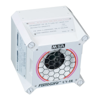
Overview of the manual's content and detector models.

Terminology

Definitions of key terms like UV, IR, IR 3 , Fire Simulator, and wiring.

Applications

Discusses various industrial applications and suitability of different models.

Specifications

References tables for technical specifications of detectors and simulators.

Section 2 FlameGard Models 805400 and 805402

Installation and Setup

Covers unpacking, mounting, guidelines, and wiring for specific models.

Control Panel Wiring

Explains various schemes for connecting detectors to control equipment.

Input Power Monitoring

Details using the accessory relay for supervision circuit supervision.

Mounting and Wiring Installation

Provides instructions for mounting the detector and conduit/wire preparation.

Function and Alarm Delay Settings

Explains configuring detector functions and alarm delays via switches.

4-20 mA Interface Wiring

Describes wiring for the 4-20 mA current output interface.

Section 3 FlameGard Models (P/Ns 805401 and 805403)

Installation and Setup

Covers unpacking, mounting, guidelines, and wiring for specific models.

Control Panel Wiring

Explains various schemes for connecting detectors to control equipment.

Mounting the Detector

Provides detailed instructions and guidelines for mounting the detector unit.

Function Switch Settings

Explains how to configure the detector using function switches.

4-20 mA Interface Wiring

Describes wiring for the 4-20 mA current output interface.

Section 4 FlameGard IR 3 Model (P/N 805399)

Installation and Setup

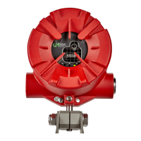
Covers unpacking, mounting, guidelines, and configuration for IR 3 model.

Guidelines and Wiring

General installation procedures, location optimization, and wiring details.

Control Panel Wiring

Explains various schemes for connecting detectors to control equipment.

Monitoring and Supervision

Details fault supervision and 4-20 mA signal monitoring.

Mounting and Initial Setup

Provides instructions for mounting and configuring the detector via switches.

Switch Functions and Built-in Test

Explains SW1 switch functions, alarm latching, and built-in test features.

Detector Sensitivity and SW1 Settings

Details sensitivity levels and guides SW1 switch selection.

SW2 and SW3 Switch Settings

Guides setting RS-485 addresses (SW2) and alarm delay (SW3).

Section 5 Operation and Maintenance

Operation

Covers initial power-on sequence, calibration, and status indicators.

Initial Testing Procedures

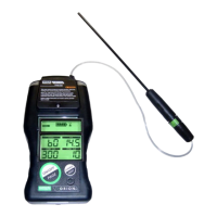
Guides testing detectors using a flame simulator before system operation.

Maintenance Procedures

Information on performing maintenance, records, and preventive cleaning.

Appendix A FlameGard Installation Outline

Related product manuals