

V
Victoria RichardsonJul 27, 2025
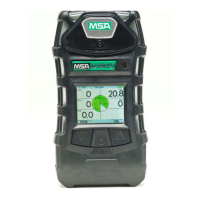
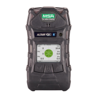
What to do if my MSA ALTAIR 5X Security Sensors show a BATTERY ALARM?
- GGeorge DoyleJul 27, 2025
If your MSA Security Sensors display a BATTERY ALARM, it means the device is no longer sensing gas. Remove it from service, and recharge or replace the battery.