English
Test bench MS008
8
3 – Protective housing. When the protective housing is up, the diagnostics will be blocked.
4 – Power cables В+, В-.
5 – Front panel.
6 – Battery location section.
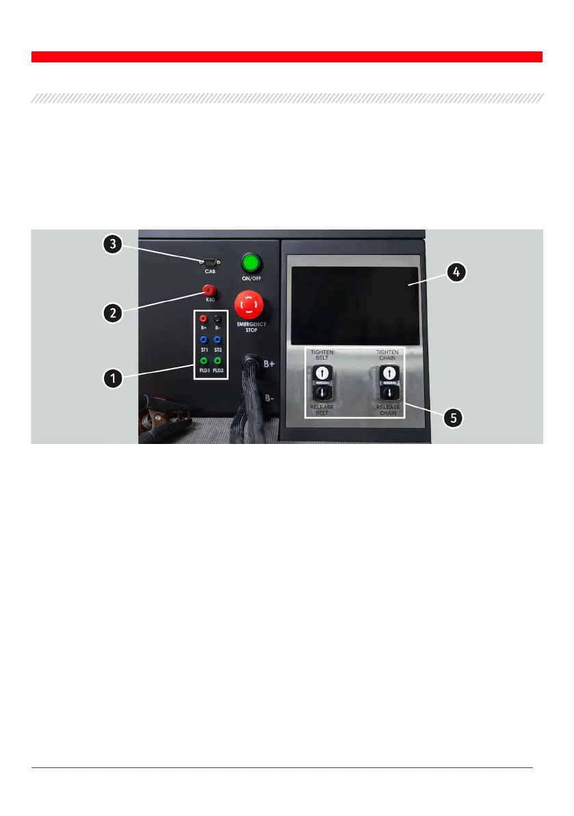
There are the following diagnostic cable connection ports on the front panel:
Figure 2. Bench front panel
1 – Connection ports used for diagnostics of voltage regulators:
• В+ – voltage regulator positive (terminal 30 and terminal 15);
• В- – voltage regulator negative (earth, terminal 31);
• ST1, ST2 –
ports for voltage regulator stator inputs (terminals) connection: P, S, STA, Stator;
• F1, F2 – ports for the connection of voltage regulator brushes or relevant terminals: DF, F,
FLD.
2 – Port for the connection of diagnostic cable to the starter terminal 50.
3 – Diagnostic cable connection port.
4 – Touch screen - to display diagnostic parameters of a diagnosed unit and to control the bench
functions.
5 – Buttons to control the tightening and loosening of alternator drive belt and unit fixing chain.
Button „OFF/ON”– is responsible for the power on the bench. The bench is turned off by pressing
the button “Turn off the bench” in the main menu of the service program.
Button „EMERGENCY STOP” – emergency stop of generator drive and chain/belt tightening.