14
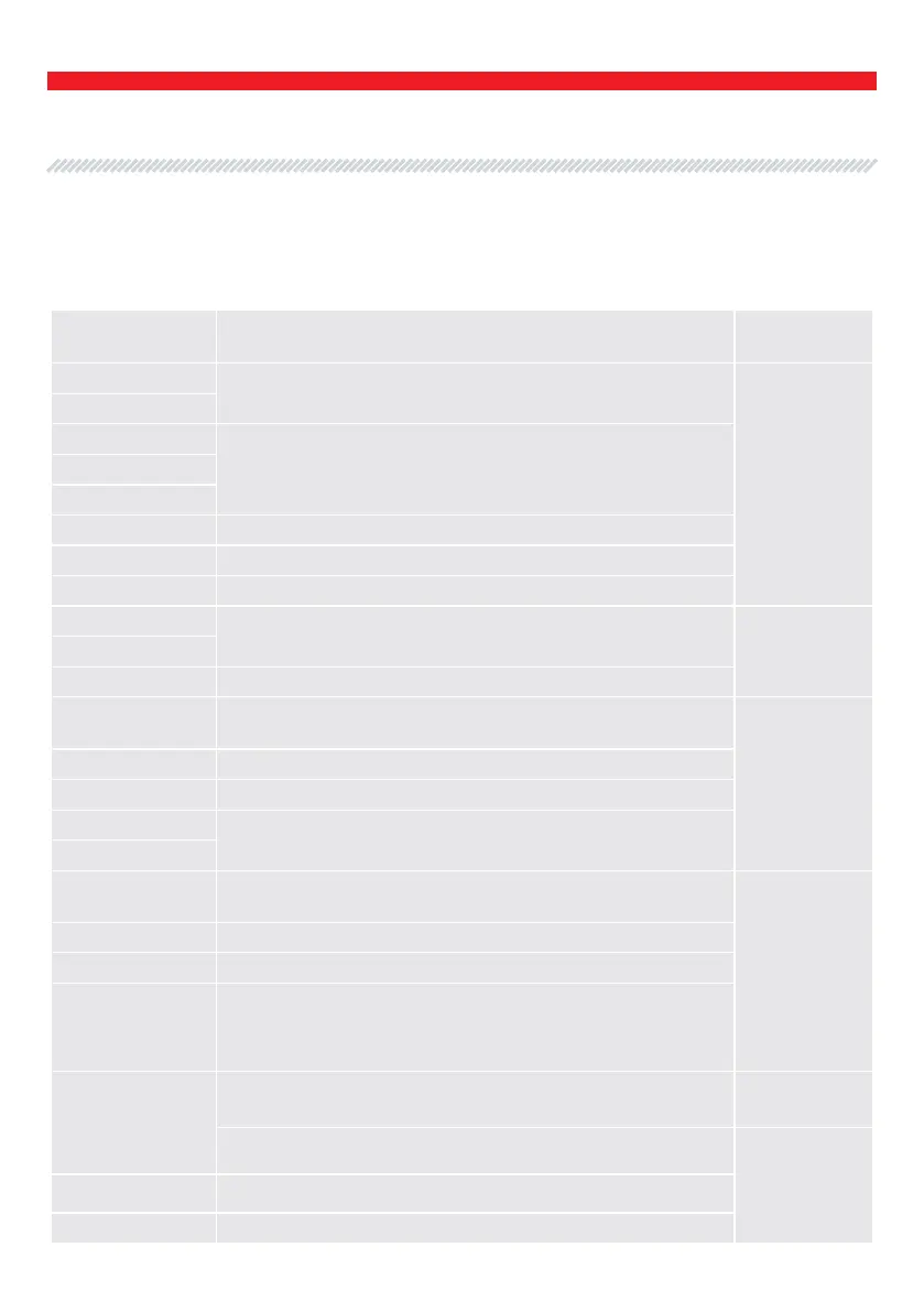
Indicial notation Functional purpose Terminal
B+
Battery (+)
B+
30
A
(Ignition) Input for switch startingIG
15
AS Alternator Sense
BVS Battery Voltage Sense
S (Sense) Input for voltage comparison at control point
B-
Battery (-)
B-31
E Earth, battery (-)
D+
Used for connection to an indicator lamp that transfers
initial driving voltage, and indicates alternator operability
L/D+
I Indicator
IL Illumination
L
(Lamp) Output for alternator operability indicator lamp
61
FR
(Field Report) Output for load control on an alternator by
engine management block
FR
DFM Digital Field Monitor
M Monitor
LI
(Load Indicator) Same as FR, but with universal signal (Drive)
Input of voltage regulator control with P-D terminals
Mitsubishi
D
(Drive) Input of voltage regulator control with terminal P-D
Mitsubishi (Mazda) and Hitachi (Kia Sephia 1997-2000)
GC
(Digital) Input of code voltage installation on American Ford,
same as SIG
GC
RC (Regulator Control) same as SIG
SIG (Signal) Input of code voltage installation
APPENDIX 1
Terminals for connection to alternators
User Manual - MS015 COM Tester
English