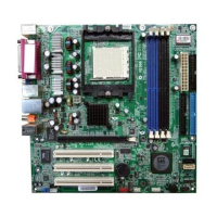
This document describes the MS-7184 (v1.X) AmethystM Micro ATX Mainboard, an ATI RS482 + SB400 based motherboard designed for high-performance and professional desktop platform solutions.
Function Description
The MS-7184 Series mainboard serves as the central component of a computer system, providing the necessary infrastructure for the CPU, memory, expansion cards, and various peripheral devices to communicate and operate. It supports AMD Athlon64 processors and features integrated graphics, sound, and network capabilities. The board's design adheres to the Micro ATX form factor, making it suitable for compact desktop systems.
Important Technical Specifications
CPU:
- Supports 64-bit AMD Athlon 64 and Athlon 64 FX processors (Socket 939).
- Compatible with CPUs up to Athlon 64 FX-55 or higher (refer to MSI's website for the latest CPU support list).
- Requires a heat sink and cooling fan for proper operation to prevent overheating.
Chipset:
- ATI RS482 Chipset:
- HyperTransport™ connection to AMD K8 Athlon64 processor.
- 8 or 16-bit control/address/data transfer in both directions.
- 1000/800 MHz "Double Data Rate" operation in both directions.
- Compliant with PCI Express 1.0a specifications, featuring one x16 graphics interface (divisible for other devices).
- Integrated graphics.
- ATI SB400 Chipset:
- Supports dual-channel native SATA controller up to 150MB/s with RAID 0, RAID 1, or RAID 0+1.
- Integrated Hardware Sound Blaster/Direct Sound AC97 audio.
- Ultra DMA 33/66/100 master mode PCI EIDE controller.
- ACPI & PC2001 compliant enhanced power management.
- Supports USB2.0 up to 8 ports.
Main Memory:
- Supports dual channel, eight memory banks DDR 333/400.
- Four 184-pin DDR DIMM slots.
- Maximum memory size up to 4GB without ECC.
- Supports 2.5V DDR SDRAM DIMMs.
- Memory modules of the same type and density are required for dual-channel DDR operation.
- Memory modules should be inserted into Channel A slots (DIMM1 or DIMM3) first for successful system boot-up.
- Does not support memory modules with more than 18 pieces of IC (integrated circuit).
- Does not support three memory modules.
Slots:
- One PCI Express x16 slot (supports PCI Express Bus specification v1.0a compliant).
- Three 32-bit Master 3.3V/5V PCI Bus slots.
Onboard IDE:
- An IDE controller on the ATI SB400 chipset provides PIO, Bus Master, and Ultra DMA 100/66/33 operation modes.
- Can connect up to 4 IDE devices.
Onboard Serial ATA:
- Supports 2 SATA ports with up to 150MB/s transfer rate.
- SATA hard drives cannot be used for OS installation in Windows ME or Windows 98; they function as ordinary storage devices under these OS.
- For creating a bootable RAID volume in Windows 2000, Microsoft's Windows 2000 Service Pack 4 (SP4) is required. A combination installation CD must be created.
USB Interface:
- 8 USB ports: 4 in the rear I/O, 4 via an external bracket.
- USB 2.0 technology offers a maximum throughput of 480Mbps.
LAN:
- Realtek 8100C 10/100 LAN chip.
- Integrated Fast Ethernet MAC and PHY.
- Supports 10Mb/s and 100Mb/s.
- Compliance with PCI v2.2.
- Supports ACPI Power Management.
IEEE 1394:
- VIA 6307 IEEE 1394 controller.
- Supports up to two 1394 ports (rear panel x 1, pinheader x 1).
- Transfer rate up to 400Mbps.
Audio:
- RealTek ALC658C 6-channel software audio codec.
- Compliance with AC97 v2.3 Spec.
- Meets PC2001 audio performance requirement.
On-Board Peripherals:
- 1 floppy port (supports 360K, 720K, 1.2M, 1.44M, and 2.88Mbytes FDD).
- 1 VGA port.
- 1 SPDIF-Out connector.
- 1 parallel port (supporting SPP/EPP/ECP mode).
- 8 USB2.0 ports (Rear4/Front4).
- 1 Audio (Line-In/Line-Out/MIC) port.
- 1 RJ-45 LAN Jack.
- 2 IDE ports (support 4 IDE devices).
- 2 serial ATA ports.
- 2 IEEE1394s (Rear * 1 / Front * 1).
BIOS:
- "Plug & Play" BIOS for automatic detection of peripheral devices and expansion cards.
- Desktop Management Interface (DMI) function to record mainboard specifications.
- Supports boot from LAN, USB Device 1.1 & 2.0, and SATA HDD.
Dimension:
- Micro-ATX Form Factor: 24.4cm X 24.4cm.
- 8 mounting holes.
Usage Features
CPU Installation:
- Socket-939 for easy CPU installation.
- Requires careful alignment of the CPU's gold arrow with the socket's orientation.
- The CPU must be firmly pressed into the socket, and the lever closed to ensure complete embedding of pins.
Memory Installation:
- DDR DIMMs have a single notch for correct orientation.
- Modules are inserted vertically and pushed until the golden finger is deeply inserted and plastic clips automatically close.
- For dual-channel mode, memory modules of the same type and density are required.
- Always insert modules into Channel A slots (DIMM1 or DIMM3) first.
Power Supply:
- Supports ATX power supply.
- ATX 24-pin power connector (ATX1) and ATX 12V power connector (JPW1) are used.
- The 24-pin connector is compatible with 20-pin ATX power supplies by aligning with pin 1 & pin 13.
- Both ATX1 and JPW1 must be connected for stable operation.
- A power supply of 350 watts (and above) is highly recommended.
- ATX 12V power connection should be greater than 18A.
Peripheral Connections:
- Floppy Disk Drive Connector (FDD1): Standard connector for various floppy disk types.
- Fan Power Connectors (CFAN1 / SFAN1): Supports system cooling fans with +12V. Red wire is positive (+12V), black wire is Ground (GND). Fans with speed sensors are needed for CPU fan control.
- ATA100 Hard Disk Connectors (IDE1 & IDE2): IDE1 is primary, IDE2 is secondary. Master/Slave configuration is required for two devices on a single cable.
- Serial ATA Connectors (SATA1~SATA2): High-speed interface for hard disk devices. SATA cables should not be folded into 90-degree angles to prevent data loss.
- CD-In Connector (JCD1): For CD-ROM audio.
- Aux Line-In Connector (JAUX1): For DVD add-on cards with Line-in connectors.
- Front Panel Audio Connector (JAUD1): Connects to front panel audio. If not connected, pins 5 & 6, 9 & 10 must be jumpered for rear audio ports to function.
- IEEE 1394 Connectors (J1394_1): For external IEEE1394 bracket.
- FWH/LPC Debugging Pin Header (JLPC1): For internal debugging only.
- Front Panel Connectors (JFP1): For front panel switches and LEDs.
- Front USB Connectors (JUSB1 / JUSB2): For external USB 2.0 devices. VCC and GND pins must be connected correctly to avoid damage.
Jumpers:
- Clear BIOS Password Jumper (JPWD1): Used to clear the BIOS password by opening the jumper and restarting the computer.
- Clear CMOS Jumper (JCMOS1): Used to clear system configuration data stored in CMOS RAM. To clear, switch off the system, short pins 2-3 of JCMOS1, switch on until "CMOS checksum error" appears, switch off, return to 1-2 pin (Keep Data), then switch on for operation. Clearing CMOS while the system is on will damage the mainboard.
Maintenance Features
Technical Support:
- Users can contact their place of purchase or local distributor for system problems.
- MSI homepage & FAQ site (http://www.msi.com.tw & http://www.msi.com.tw/program/service/faq/faq/esc_faq_list.php) provide technical guides, BIOS updates, and driver updates.
- Technical staff can be contacted at support@msi.com.tw.
Safety Instructions:
- Always read safety instructions and keep the User's Manual for future reference.
- Keep equipment away from humidity.
- Place equipment on a reliable flat surface.
- Do not cover enclosure openings to ensure proper air convection and prevent overheating.
- Verify power source voltage (110/220V) before connecting.
- Route power cord to prevent stepping or placing objects on it.
- Always unplug the power cord before inserting add-on cards or modules.
- Note all cautions and warnings on the equipment.
- Never pour liquid into openings.
- If the power cord/plug is damaged, liquid penetrates, equipment is exposed to moisture, equipment malfunctions, or shows signs of damage, have it checked by service personnel.
- Do not store equipment in unconditioned environments above 60°C (140°F) to prevent damage.
Battery Replacement:
- Danger of explosion if battery is incorrectly replaced.
- Replace only with the same or equivalent type recommended by the manufacturer.
- Waste batteries should be collected separately for recycling or special disposal for environmental protection.
BIOS Update:
- Each board has a unique 1394 GUID from default BIOS settings.
- Use flash utility or Live Update from MSI's website for BIOS updates.
- If the 1394 GUID address is lost (e.g., due to a new BIOS chip), users can use a utility from MSI's website to recover it by entering the original GUID address.
Overheating Prevention:
- Overheating can seriously damage the CPU and system.
- Ensure the cooling fan works properly to protect the CPU.
CPU Replacement Safety:
- Always turn off the ATX power supply or unplug the power supply's power cord from a grounded outlet before replacing the CPU.
Overclocking:
- The motherboard supports overclocking, but users should ensure components can tolerate abnormal settings.
- Operating beyond product specifications is not recommended, and MSI does not guarantee against damages or risks from inadequate operation or exceeding specifications.
FCC-B Radio Frequency Interference Statement:
- Equipment complies with class B digital device limits (Part 15 of FCC rules).
- Designed to provide reasonable protection against harmful interference in a commercial environment.
- May cause harmful interference if not installed/used according to the manual.
- In residential areas, users may need to correct interference at their own expense.
- Changes/modifications not approved by the party responsible for compliance could void user's authority to operate.
- Shielded interface cables and A.C. power cord (if any) must be used to comply with emission limits.
- Device complies with Part 15 of FCC Rules: (1) may not cause harmful interference, and (2) must accept received interference.