○○○○○○○○○○○○○○○○○○○○○○○○○
2-16
Chapter 2
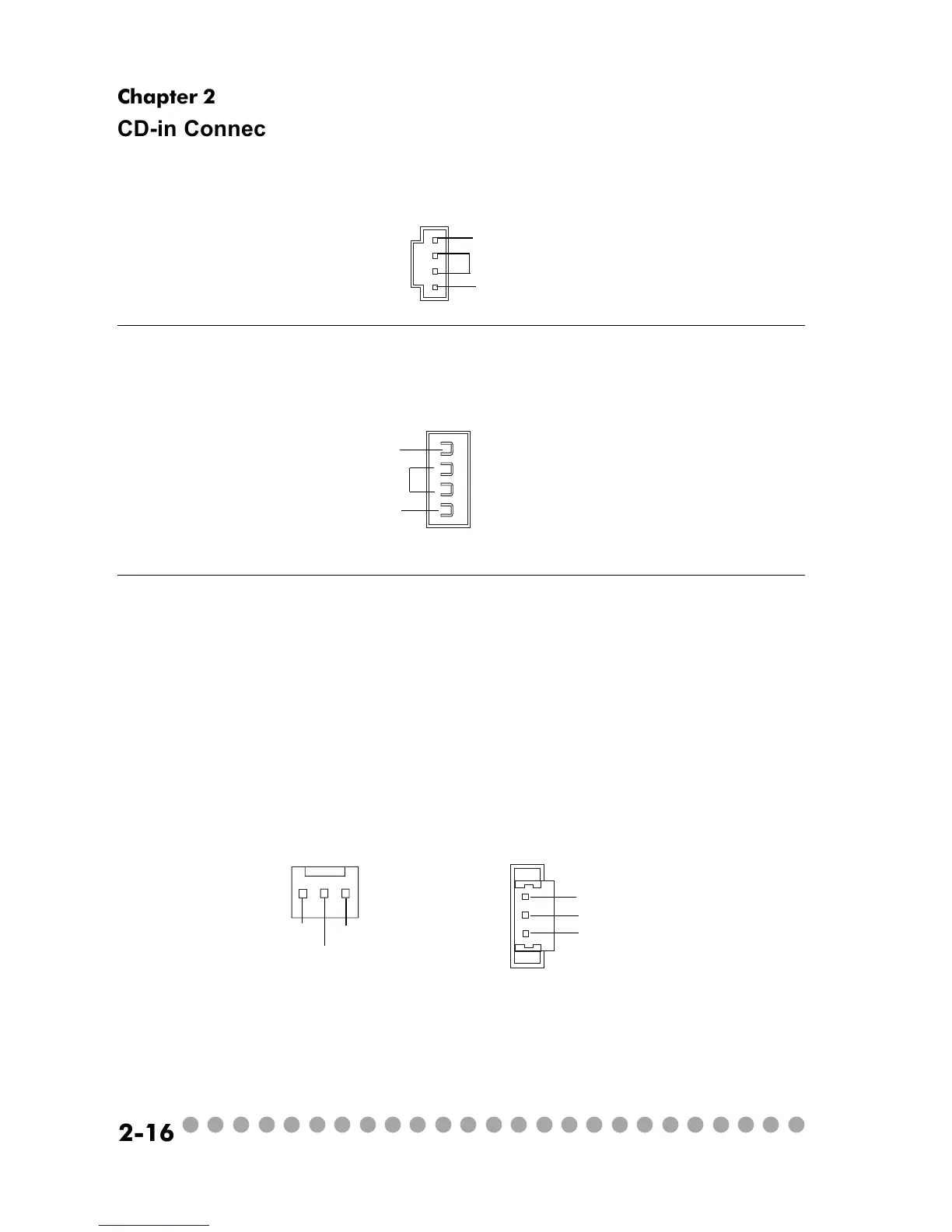
CD-in Connector: JCD1
The connector is for CD-ROM audio connector.
CPU/System Fan Connectors: CPUFAN1/CN31/CN30
The CPU and System Fan connectors support system cooling fans with
+12V that is controlled by PWM. When connecting the wire to the three-pin
head connectors, always note that the red wire is the positive and should be
connected to the +12V (that is controlled by PWM), the black wire is Ground
and should be connected to GND.
JCD1
GND
R
L
CPUFAN1 CN30/CN31
SENSOR
+12V
GND
+12V
SENSOR
GND
Standby Power Connector: U11
The mainboard provides a connector to connect the Standby power.
+12VSBY
GND
5VSB