○○○○○○○○○○○○○○○○○○○○○○○○○
2-17
Introducing Mainboard
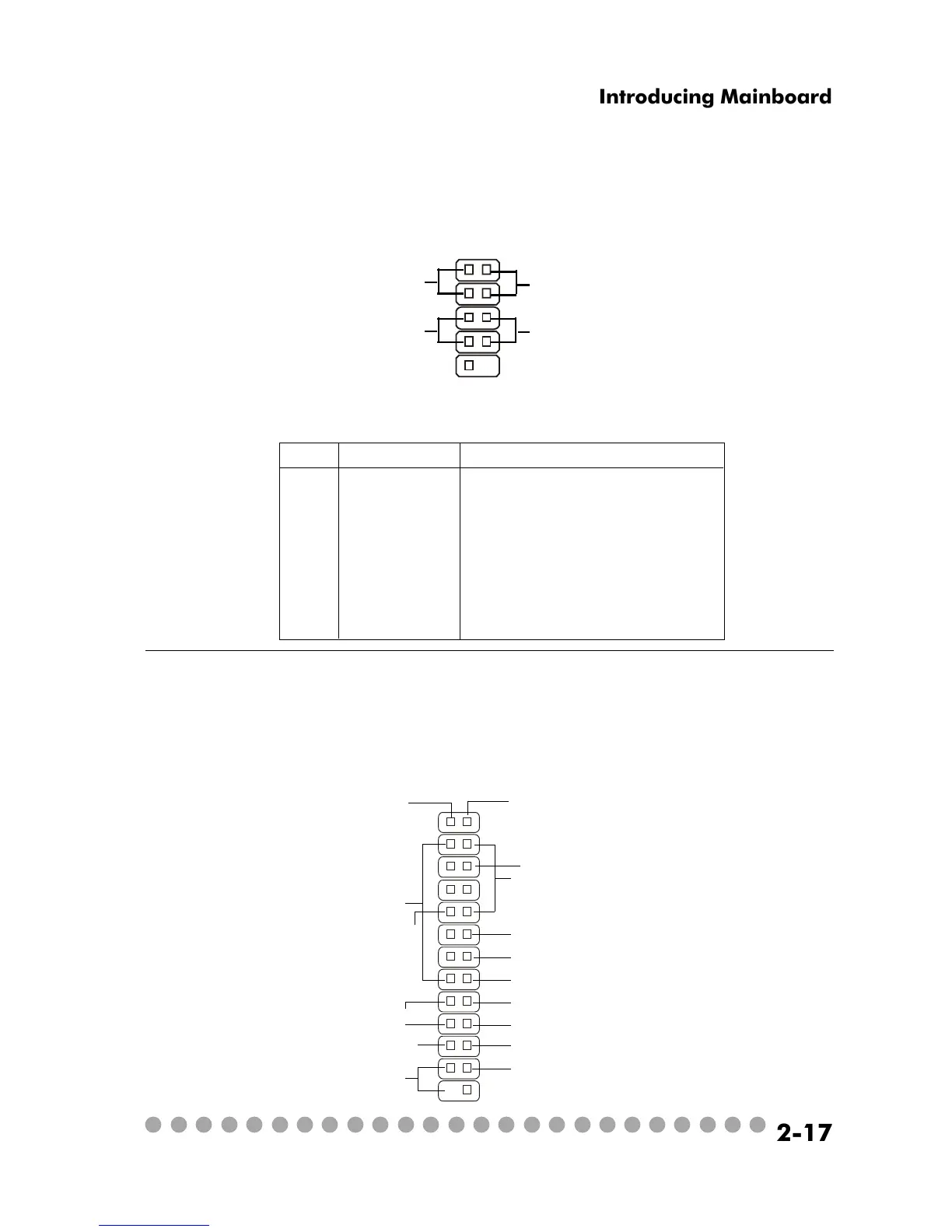
Front Panel Power Connector: JFP1
The mainboard provides a Front Panel connector for electrical connec-
tion to the Front Panel switches and LEDs. JFP1 is compliant with Intel
®
Front
Panel I/O Connectivity Design Guide.
PIN SIGNAL DESCRIPTION
1 HD_LED_P Hard disk LED pull-up
2 FP PWR/SLP MSG LED pull-up
3 HD_LED_N Hard disk active LED
4 FP PWR/SLP MSG LED pull-up
5 RST_SW_N Reset Switch low reference pull-down to GND
6 PWR_SW_P Power Switch high reference pull-up
7 RST_SW_P Reset Switch high reference pull-up
8 PWR_SW_N Power Switch low reference pull-down to GND
9 RSVD_DNU Reserved. Do not use.
JFP1 Pin Definition
1
910
JFP1
HDD
LED
Reset
Switch
Power LED
Power
Switch
2
Control Board Connector: J8
The connector is used to connect the Control Board on the front panel.
J8
1
25
26
VCC3SBY
2
SPI Bus
CD_SMI
VCC5
HDLED
PWRBTNH
FP_RST
Power LED
LED-BL
VCC5SBY
IR
GND
GND
Key (0-~5)
GND
+12VSBY
Power LED