Do you have a question about the MSI MPC 400 and is the answer not in the manual?
Details FCC compliance for Class B digital devices and potential interference issues.
States that unauthorized modifications can void user authority to operate equipment.
Advises using shielded cables and power cords for emission compliance.
Cautionary statement regarding the danger of explosion if battery is incorrectly replaced.
Information on copyright protection technology used in the product.
Comprehensive list of safety instructions for equipment setup, operation, and maintenance.
Specific warning about the danger of explosion from improper lithium battery replacement.
Lists registered trademarks and their respective owners.
Records the revision history of the user guide, including dates and descriptions.
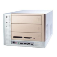
Provides a brief overview of the MPC 400's design and features.
Lists the technical specifications of the MPC 400 system.
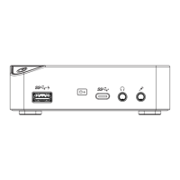
Identifies and illustrates the ports and controls located on the front panel of the MPC 400.
Illustrates the various ports and connectors on the back panel of the MPC 400.
Alerts users to check and select the correct AC power voltage switch on the back panel.
Details the motherboard, CPU socket, and chipset used in the MPC 400.
Outlines memory support, on-board audio, VGA, and communication features.
Lists expansion slot types, power supply details, and chassis dimensions.
Provides a diagram and overview of the mainboard's layout and components.
Discusses CPU support, socket type, and installation considerations.
Details memory slots, type, and maximum supported memory capacity.
Describes the power supply unit and its connectors.
Explains the front panel connectors and their functions.
Details the ports and connectors found on the back panel.
Lists and describes various internal and external connectors on the mainboard.
Explains the function and configuration of system jumpers.
Describes the expansion slots available on the mainboard.
Detailed labeling and identification of components on the MS-6749 v1.X Mainboard.
Discusses CPU socket type and critical thermal management for processor operation.
Explains how to configure CPU clock frequency through jumpers.
Step-by-step guide for safely installing a CPU into the socket, including orientation and lever operation.
Explains the characteristics and benefits of DDR SDRAM technology.
Provides guidance on installing DIMM modules in available slots for optimal configuration.
Details the pin assignments for the 20-pin JWR1 and 4-pin JPW1 power connectors.
Lists the technical specifications of the 200W ATX power supply unit.
Identifies the ports on the front panel, including Optical SPDIF-in, Mic-in, Head-Phone, USB, and IEEE 1394 ports.
Describes the smaller IEEE 1394 port and its connectivity for external powered devices.
Explains the larger 6-pin IEEE 1394 port for devices requiring power from the mainboard.
Details the USB ports, their function, and the pinout description for USB devices.
Describes the connectors for microphone input and headphone/speaker output.
Explains the optical connector for SPDIF audio interface for recording and playback.
Details the 9-pin male DIN serial port, its diagram, and pinout for connecting serial devices.
Provides pin definitions for the PS/2 connectors used for keyboards and mice.
Details the 15-pin female VGA connector and its pinout for monitor connection.
Describes the RJ-45 LAN port and its pinout for network connectivity.
Explains the S-Video out connector for video output to TVs or video devices.
Describes the optical connector for SPDIF audio output, supporting Dolby Digital.
Details the 25-pin female parallel port, its diagram, and pinout for printer connections.
Provides further details on USB port functionality and pin descriptions.
Explains usage of audio ports for stereo and 5.1 channel audio output.
Describes the primary and secondary IDE connectors and their device limitations.
Identifies the connector for CD-ROM audio input.
Details the connector used to connect the standby power supply.
Describes the 3-pin connectors for CPU and system cooling fans.
Details the pin assignments for the front panel power and LED connections.
Identifies the connector for interfacing with the control board on the front panel.
Explains how to use the JBAT1 jumper to clear CMOS settings.
Describes the J1 jumper used to set the CPU Front Side Bus mode.
Details the PCI slot for inserting PCI cards or TV tuner cards.
Describes the AGP slot for graphics card installation and its specifications.
Guides on how to enter the BIOS setup utility upon system startup.
Introduces the main menu structure and navigation options within the BIOS setup.
Outlines the basic system configurations available in the Standard CMOS Features menu.
Details the advanced features and settings accessible through the Advanced BIOS Features menu.
Explains how to adjust chipset registers to optimize system performance.
Covers settings related to ACPI power management modes and events.
Describes settings for Plug and Play and PCI device configurations.
Details settings for onboard peripherals like IDE, LAN, Audio, and USB controllers.
Provides information on monitoring system voltages, temperatures, and fan speeds.
Shows system status details such as BIOS version, processor type, and memory.
Explains the POST process and the key to press for entering BIOS setup.
Lists and describes the keyboard keys used for navigating and making changes within the BIOS setup utility.
Guides on navigating the main menu and accessing sub-menus for detailed settings.
Explains how to access the general help screen using the F1 key for assistance.
Introduces the menu for basic system configurations like time and date.
Covers settings for enhanced system features and boot behavior.
Details options for optimizing system performance by adjusting chipset registers.
Explains settings for managing system power consumption.
Options for configuring Plug and Play and PCI devices.
Settings for enabling or disabling onboard integrated peripherals.
Displays real-time monitoring of system hardware status like temperatures and voltages.
Provides detailed information about the system's hardware components.
Options to set supervisor or user passwords for BIOS access security.
Options to load default settings or save changes and exit the BIOS utility.
Allows setting the system's current time and date.
Configuration for primary and secondary IDE drives, including manual definition.
Input fields for defining manual IDE drive parameters like cylinders, heads, and sectors.
Allows changing the display language of the BIOS setup utility.
Options to speed up boot time by skipping checks and enable/disable company logo display.
Enables virus warning for IDE Hard Disk boot sector protection.
Defines the sequence of devices the system attempts to boot from.
Activates Self-Monitoring Analysis and Reporting Technology for hard disk health prediction.
Sets the initial state of the Num Lock key upon system power-on.
Specifies the type of BIOS password protection implemented.
Options for OS/2 boot support and enabling/disabling the APIC interrupt controller.
Allows selection of the Multi-Processor Specification version for operating system compatibility.
Settings for Spread Spectrum feature and PCI delayed transactions.
Entry point to configure DRAM timing parameters.
Entry point to configure AGP timing parameters.
Option to let BIOS automatically determine DRAM timings via SPD.
Settings for SDRAM clock frequency and CAS# latency timing.
Options for configuring SDRAM bank interleave for performance optimization.
Settings for SDRAM burst length and command rate for performance tuning.
Controls CPU internal timing and enables AGP Fast Write for improved graphics performance.
Allows allocation of system RAM to AGP for video purposes.
Options to insert wait states into AGP read/write cycles.
Settings for AGP read synchronization and on-chip VGA frame buffer size.
Options to select the boot display device and TV signal format.
Allows selection of the TV output connector type, S-Video or Composite.
Specifies the ACPI power saving modes for the system.
Configures system wake-up events based on hardware activity.
Enables scheduled system resume by alarm date, hour, minute, and second.
Resets the ESCD NVRAM, which stores resource information for devices.
Controls the onboard IDE controller and onboard LAN controller.
Manages LAN power features and boot ROM functionality.
Enables onboard AC'97 audio and controls the 1394 device.
Manages USB controllers and legacy support for older USB devices.
Accesses settings for Super I/O ports like Floppy, Serial, and Parallel.
Configures base I/O port addresses and IRQ for onboard Serial Port 1.
Sets parallel port mode (ECP, EPP) and EPP version.
Displays real-time monitoring of CPU temperature, system temperature, fan speeds, and voltages.
Shows essential system information including product name, BIOS version, and processor details.