EasyManua.ls Logo

MSI MS-6119 ATX BX2 User Manual

MSI MS-6119 ATX BX2
32 pages
To Next Page IconTo Next Page
Page #1 background imageLoading...
Page #1 background image
MS-6119 ATX BX2 Mainboard
MICRO-STAR INTERNATIONAL COMPANY LTD.
Specification & User’s Guide
MS-6119 ATX BX2 Mainboard
Specification & User’s Guide
1. Introduction
The MSI ATX BX2 mainboard is a high-performance personal computer mainboard
based on the Pentium
®
II processor. The Pentium
®
II processor supports MMX
TM
(Multime-
dia Extension) technology.
The mainboard uses the highly integrated Intel
®
82443BX AGP chipset to support
the PCI/ISA and Green standards, and to provide the Host/AGP bridge. The Intel
®
82371AB chipset integrates all system control functions such as ACPI (Advanced Configu-
ration and Power Interface). The ACPI provides more Energy Saving Features for the
OSPM(OS Direct Power Management) function. The Intel
®
82371EB chipset also improves
the IDE transfer rate by supporting Ultra DMA/33 IDE that transfers data at the rate of
33MB/s.
The mainboard also supports the LM78 System Hardware Monitor Controller as an
optional function. The LM78 function includes: CPU /power supply/chassis fan revolution
detect, CPU/system voltage monitor, system temperature monitor, and chassis intrusion
detect(optional).
MICRO-STAR
INTERNATIONAL
COMPANY LTD.
MICRO-STAR
INTERNATIONAL
COMPANY LTD.
Specification & User’s Guide
1
Question and Answer IconNeed help?

Do you have a question about the MSI MS-6119 ATX BX2 and is the answer not in the manual?
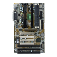
MSI MS-6119 ATX BX2 Specifications

General IconGeneral
Form FactorATX
ChipsetIntel 440BX
Memory TypeSDRAM
ISA Slots1
PCI Slots4
AGP Slots1
USB Ports2
AudioOptional
BIOSAward BIOS
Supported ProcessorsIntel Pentium II, Celeron
Memory Slots3
IDE2

Summary

1. Introduction

2. Mainboard Specification

3. Mainboard Layout

4. Backpanel Layout

Mouse Connector

Pin definition and description for the PS/2 mouse connector.

Keyboard Connector

Pin definition and description for the PS/2 keyboard connector.

USB Connectors

Pin definition and description for the USB ports on the mainboard.

Parallel Port Connector

Pin definition and description for the parallel port connector.

Serial Port Connectors

Pin definition and description for the serial port (COM A/COM B) connectors.

5. Slot 1

Slot 1 Pin Definition

6. DIMM DRAM Addressing

7. CPU Fan Power Connector

IrDA Infrared Module Connector

Diagram and description of the IrDA infrared module connector pins.

Appendix A - CPU Core Speed Derivation

Jumpers

Power On Mode Jumper: JP2

Connectors

Case Connector: JFP1

Details for the JFP1 connector block for case-mounted LEDs, switches, and speaker.

ATX 20-pin Power Connector: JWR1

Description of the ATX 20-pin power connector and its signals.

Remote Power On/Off Switch: JRMS1/JRMS2

Functionality of the JRMS1/JRMS2 switches for power control and sleep mode.

Chassis Intrusion Connector: JP3

Function of the JP3 connector for chassis intrusion detection.

Modem Wake Up Connector: JMDM1

Description of the JMDM1 connector for modem wake-up functionality.

Wake-Up on LAN connector: JWOL1

Description of the JWOL1 connector for Wake-Up on LAN functionality.

Add-On Card Sound Connector: J3

Description of the J3 connector for distributed DMA PCI sound cards.

Appendix B - Schematics

Notes (Page 26)

Appendix C - Bill for Materials

Notes (Page 28)

Appendix D - Mechanical Drawings

Notes (Page 30)

Appendix E - Test Reports

Main Office & Branch Offices

Related product manuals