En-3
Installation Guide
English
Central Processing Unit Socket En-4 DDRII Sockets : DIMM1~4 (dual channel)En-5
Fan Power Connectors En-6 Floppy Disk Driver Connector En-6
ATA 100 Hard Disk Connector En-6 Serial ATA Connector En-6
Front Panel Connectors En-7 Front USB 2.0 Connector En-7
IEEE 1394 Connector En-7 Front Panel Audio Connector En-8
CD-In Connector En-8 Chassis Intrusion Switch Connector En-8
IrDA Infrared Module Connector En-8 D-Bracket
TM
2 Connector En-9
Clear CMOS Button En-10 ATX 24-Pin Power Connector En-10
ATX 12V Power Connector (2x2-Pin) En-10 ATX 12V Power Connector (1x4-Pin) En-10
PCI Express Slot (x16/ x4/ x1) En-11 PCI Slot En-11
Mouse/ Keyboard port Connector En-12 Parallel Port Connector En-12
Serial Port Connector En-12 IEEE 1394 Port Connector En-12
LAN (RJ-45) Jack En-13 USB Connectors En-13
Green Audio Jack (Line-out) En-13 Blue Audio Jack En-13
Pink Audio Jack (Mic-In) En-13 Orange Audio Jack En-13
Black Audio Jack (Rear Surround-Out) En-13 Gray Audio Jack (Side Surround-Out) En-13
Coaxial S/PDIF-out Connector En-13
1
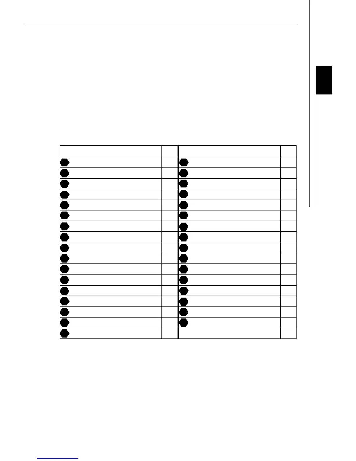
Components Index Table
3
5
7
4
6
9
8
12
14 15
19
21
16
20
25
27
29
23
26
30
31 34
35
37
39
36
38
40
41 42
43
Component Number Component Numberpage page
10
“ How to use this Installation Guide?”
This installation guide is designed for you to easily install the mainboard. Follow the steps below to use this guide:
- Read the specifications of the mainboard first on page En-1.
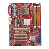
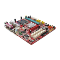
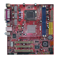
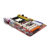
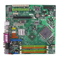
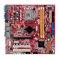
- Find out the component with the component number at your desire from the layout of the mainboard on page En-2.
- Find out the component description and installing instructions with the “Components Index Table” direction and install
it.
- Set BIOS and install the driver / utiltity at your desire.