2-14
MS-7392 Mainboard
Chassis Intrusion Switch Connector: JCI1
This connector connects to a 2-pin chassis switch. If the chassis is opened, the
switch will be short. The system will record this status and show a warning mes-
sage on the screen. To clear the warning, you must enter the BIOS utility and clear the
record.
CD-In Connector: CD_IN1
This connector is provided for external audio input.
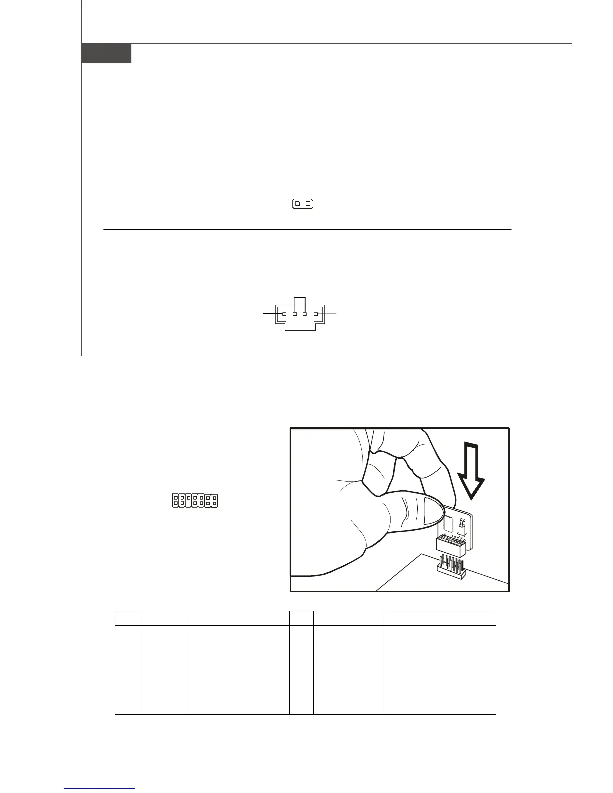
TPM Module connector: JTPM1
This connector connects to a TPM (Trusted Platform Module) module. Please refer to
the TPM security platform manual for more details and usages.
JCI1
2
G
N
D
C
I
N
T
R
U
1
CD_IN1
GND
R
L
2
1
14
13
JTPM1
Pin Signal Description Pin Signal Description
1 LCLK LPC clock 2 3V dual/3V_STB 3V dual or 3V standby power
3 LRST# LPC reset 4 VCC3 3.3V power
5 LAD0 LPC address & data pin0 6 SIRQ Serial IRQ
7 LAD1 LPC address & data pin1 8 VCC5 5V power
9 LAD2 LPC address & data pin2 10 KEY No pin
11 LAD3 LPC address & data pin3 12 GND Ground
13 LFRAME# LPC Frame 14 GND Ground
PDF created with pdfFactory Pro trial version www.pdffactory.com