2-8
Hardware Setup
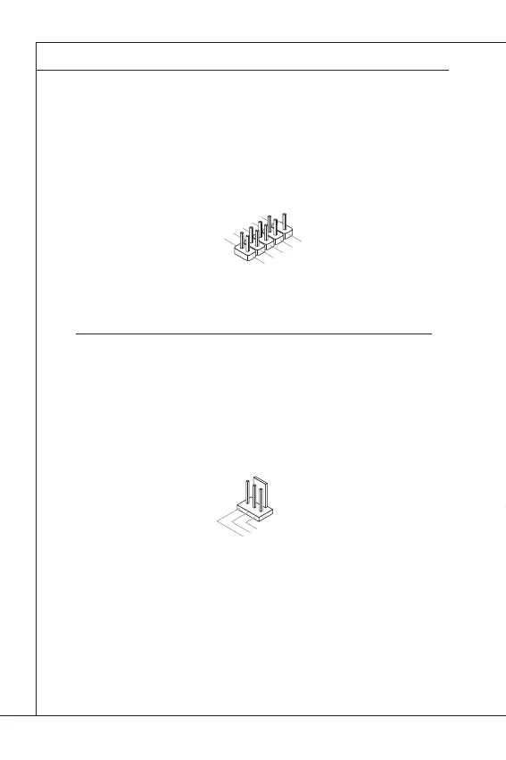
Front Panel Pinheader: JFP1
This front panel connector is provided for electrical connection to the front
panel switches & LEDs and is compliant with Intel Front Panel I/O Con-
nectivity Design Guide.
1.HDD_LED+
3.HDD_LED-
10.No
P
in
5.Reset_S
W-
7.Reset_SW+
9.Reserve
d
8.Power_S
W-
6.Power_SW+
4.Power_LED-
2.Power_LED+
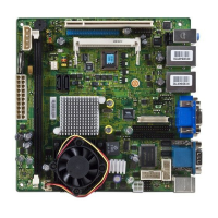
Fan Power Connectors: CPUFAN1 & SYSFAN1
These fan power connectors support system cooling fan with +12V. When
connecting the wire to the connectors, always note that the red wire is the
positive and should be connected to the +12V; the black wire is Ground and
should be connected to GND. If the mainboard has a System Hardware
Monitor chipset onboard, you must use a specially designed fan with speed
sensor to take advantage of the fan control.