13Section 2 — ASSembly & Set-Up
Skid Shoes
The snow thrower skid shoes are adjusted at
the factory, set roughly 1/8” below the shave
plate. Adjust them downward, if desired, prior to
operating the snow thrower.
CAUTION: Use extreme caution
when on gravel and adjust auger
housing height to clear gravel or
crushed rock surfaces to avoid
picking up and throwing gravel or
crushed rock.
• For close snow removal on a smooth
surface, raise skid shoes higher on auger
housing.
• Use a lower position when area to be
cleared is uneven, such as a gravel
driveway.
NOTE: If you choose to operate unit on a gravel
surface, keep skid shoes in position for maximum
clearance between ground and shave plate.
NOTE: Some models are equipped with
reversible skid shoes and may be turned over to
increase their lifespan.
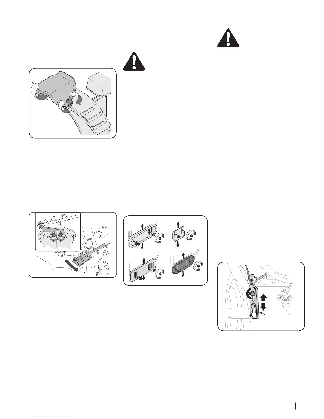
To adjust skid shoes:
1. Loosen hex nuts, washers (if equipped)
and carriage bolts. Move skid shoes to
desired position.
2. Make certain entire bottom surface of skid
shoe is against ground to avoid uneven
wear on skid shoes.
3. Retighten hex nuts, washers (if equipped)
and carriage bolts securely.
See Figure 2-44.
(a)
NOTE: Standard skid shoes shown
for illustration.
(a)
(b)
(b)
Figure 2-44
Auger Control Test
WARNING! Prior to operating
your unit, carefully read and follow
all instructions below. Perform all
adjustments to verify your
equipment is operating safely and
properly.
Refer to Controls & Operation section (page 14)
for the location of auger control lever and check
adjustment as follows:
1. When auger control lever is released and
in disengaged “UP” position, the cable
should have very little slack. It should NOT
be tight.
2. In a well-ventilated area, start the snow
thrower engine. Refer to your Engine
Operator’s Manual.
3. While standing in the operator’s position
(behind the unit), depress the auger
control lever to engage auger.
4. Allow auger to remain engaged for
approximately ten (10) seconds before
releasing auger control lever. Repeat this
several times.
5. With auger control lever in disengaged
“UP” position, walk to front of machine.
6. Confirm that auger has completely
stopped rotating and shows NO signs
of motion. If auger shows ANY signs of
rotating, immediately return to operator’s
position and shut OFF engine. Wait for ALL
moving parts to stop before readjusting
auger control lever.
7. To readjust the auger control cable, loosen
upper hex screw (a) on auger control
bracket. See Figure 2-45.
8. Position bracket upward to provide more
slack (or downward to increase cable
tension). See Figure 2-45. Retighten upper
hex screw (a).
9. Repeat Steps 2 through 6 to verify proper
adjustment has been achieved.
Figure 2-45
Adjustments
Chute Assembly
On units with manual chute tilt, the distance
snow is thrown can be adjusted by changing
angle of chute assembly. To do so:
1. Loosen wing knob found on left side of
chute assembly. See Figure 2-42.
Figure 2-42
2. Pivot chute upward or downward before
retightening wing knob.
Chute Bracket (If Equipped)
If spiral at bottom of the chute directional
control is not fully engaging with chute
assembly, chute bracket needs to be adjusted.
To do so:
1. Loosen two nuts (a) which secure chute
bracket and reposition it slightly. See
Figure 2-43.
Figure 2-43
2. Retighten nuts.
 Loading...