Cylinder head
105
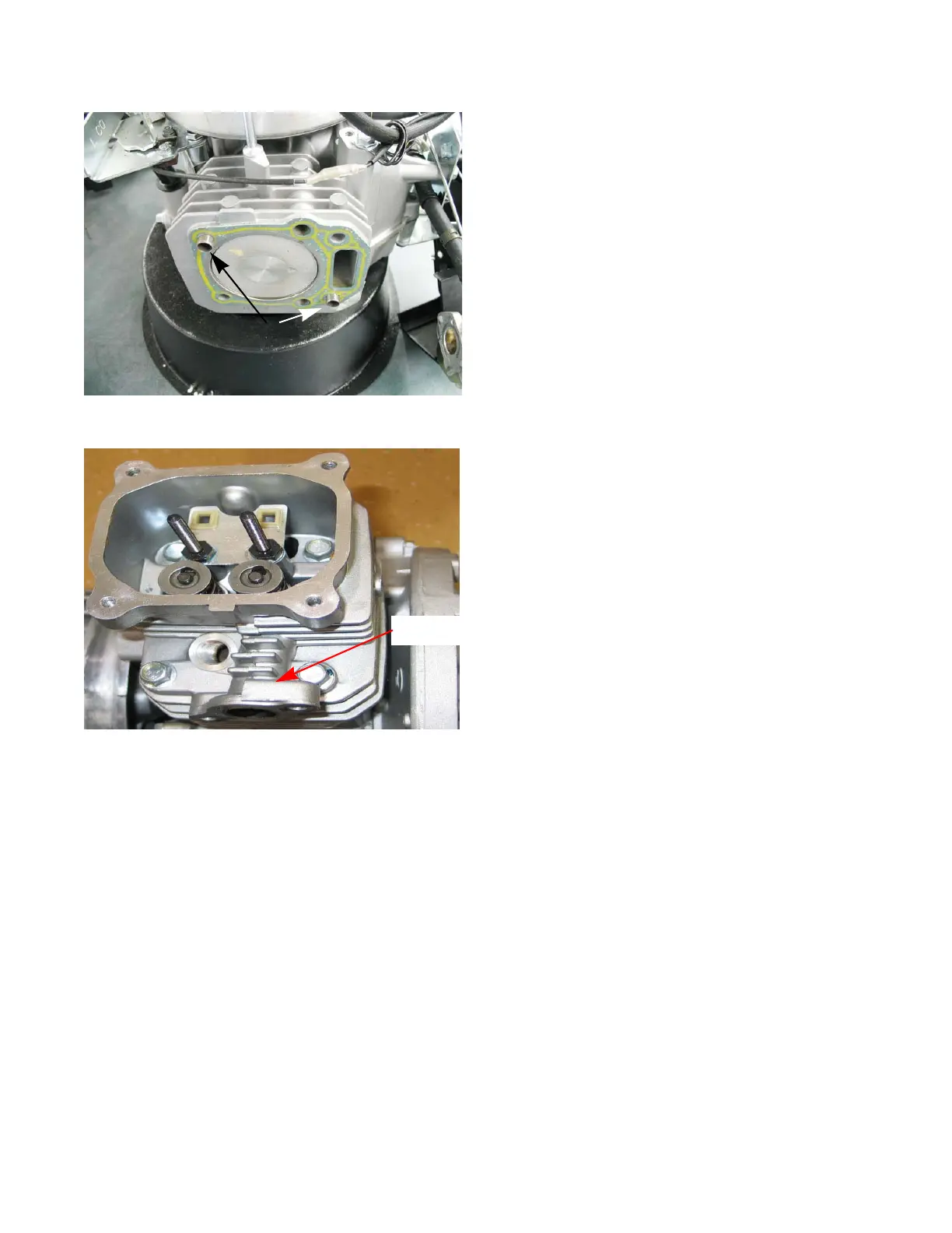
NOTE: Current production has the dowels on a diagonal.
See Figure 9.6.
12. Carefully clean all sealing surfaces of all gasket resi-
due. Do not scratch the sealing surfaces.
NOTE: Make a visual inspection of the valves and cylinder
bore to confirm the initial diagnosis.
13. Place a new head gasket on the cylinder, allowing the
alignment dowels to hold it in place.
NOTE: Early production used siliconized head gasket.
Current production uses a graphite gasket and it is
a direct replacement for the older head gasket.
The graphite gasket is a one time use only gasket
and must be replaced any time the cylinder head
bolts are loosened.
14. Position the cylinder head on the engine block.
15. Install the 4 head bolts, and tighten them to a step
torque of 212 in lb. (24 Nm) in an alternating diagonal
pattern. See Figure 9.7.
NOTE: The bolt closest to the exhaust valve must be the
last bolt tightened. Failure to do so will result in the
head bolt loosening up.
16. Insert the push rods.
17. Install the rocker arms. Adjust the valve lash by fol-
lowing the steps described in Chapter 1: Introduction.
18. Install the carburetor and air cleaner, using new gas-
kets, by following the steps described in Chapter 3:
Air Intake
19. Install the muffler by following the steps described in
Chapter 8: Exhaust.
20. Test run the mower in a safe area before returning it
to service. Check all safety features.
Figure 9.6
Alignment dowels
Figure 9.7
3
4
1
2
Exhaust
port

 Loading...


