Ignition System
89
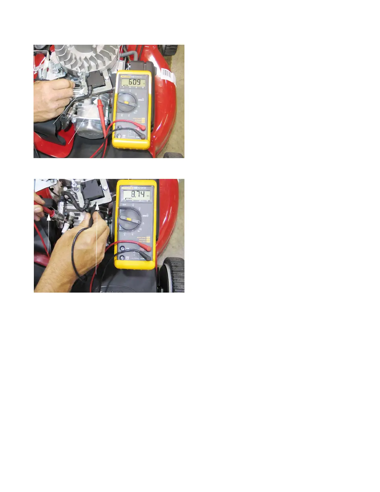
10. Resistance in the primary windings of the ignition
module, measured between the spade terminal and
the laminations, was observed to be in the 550-650
range. See Figure 7.11.
10a. Resistance in the secondary windings of the
ignition module, measured between the spark
plug terminal and the laminations, was
observed to be in the 8K-9Krange. See
Figure 7.12.
NOTE: There may be slight variation in specification due
to production variation and other factors such as
temperature.
• Resistance figures that are vastly lower may indi-
cate a short in the windings being tested.
• Resistance figures that are vastly higher (or O.L)
may indicate a fault in the windings being tested.
Figure 7.11
Probe to
laminations
Probe to stop switch
spade terminal
Figure 7.12
Probe to spark
plug terminal
Probe to laminations