AIR INTAKE SYSTEM
35
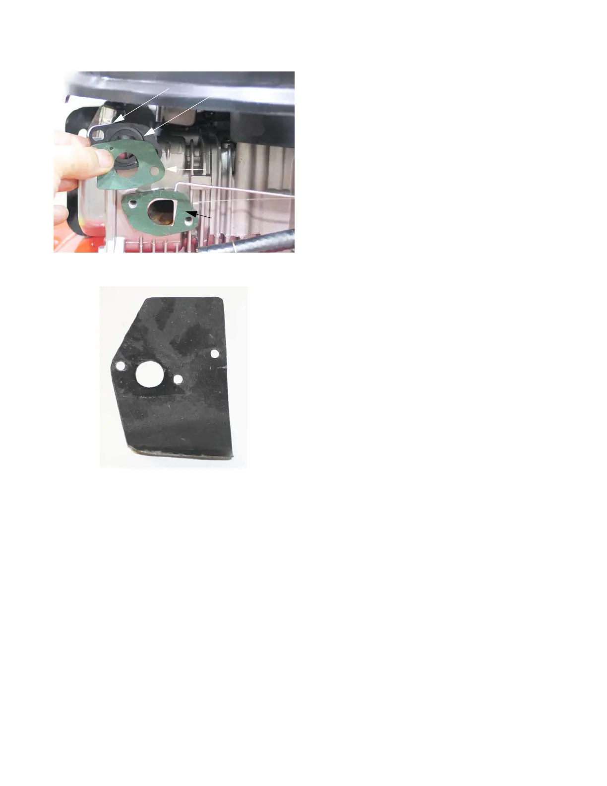
3. The insulator is sandwiched between two gaskets
which are located between the carburetor and the
cylinder head. See Figure 3.17.
NOTE: The gaskets are different, and there is an orienta-
tion to the insulator.
NOTE: On some engines, the insulator to cylinder head
gasket is a graphite gasket/heat shield. See Figure
3.18.
• If the gasket has a “D” shaped opening, it goes
between the insulator and the cylinder head.
• Match the shape of the gasket to the shape of the
intake port.
• The bowl vent channel in the insulator faces the
carburetor, with the exit toward the bottom.
• There is a small hole in the insulator to carburetor
gasket. The hole should be aligned to allow pas-
sage of air through the bowl vent channel to the
throttle side bowl vent in the carburetor body.
4. Install the insulator by following the above steps in
reverse order.
NOTE: Tighten the carburetor mounting nuts to a torque of
80 - 106 in lbs (9 - 12 Nm).
5. Test run the engine before returning to service.
Figure 3.17
Gasket: insulator
to cylinder head
Gasket: Insulator
to carburetor
Insulator
Bowl vent channel
 Loading...


