5.
Lubricate all lubrication points.
NOTE: Use a pressure washer or garden hose is not
recommended to clean your tractor. They may cause
damage to electrical components, spindles, pulleys,
bearings or the engine. The use of water will result in
shortened life and reduce serviceability.
RemovingTheTractorFromStorage
1. Check the engine oil.
2. Fully charge the battery and inflate the tires to the
recommended pressure.
3. If drained before storing, fill the fuel tank with clean, fresh
gasoline.
4. Add clean, fresh fuel.
5. Start the engine and allow to idle for afew minutes to ensure
engine is operating properly.
6. Drive the tractor without a load to make certain all the tractor
systems are functioning properly.
Adj.stments
Adjusting the Seat
To adjust the position of the seat, pull up and hold the seat
adjustment lever. Slide the seat forward or rearward to the
desired position; then release the adjustment lever. Make sure
seat is locked into position before operating the tractor. See Fig.
6-5.
k_ j
Figure 6-4
Adjusting RH& LHDriveControl Levers
The RH and LH drive control levers can be adjusted up or down
and fore-and-aft for the comfort of the operator. The drive
control levers can be placed in either of two height positions,
and/or can be moved forward or rearward within the range of
the slot in each control lever mounting bracket.
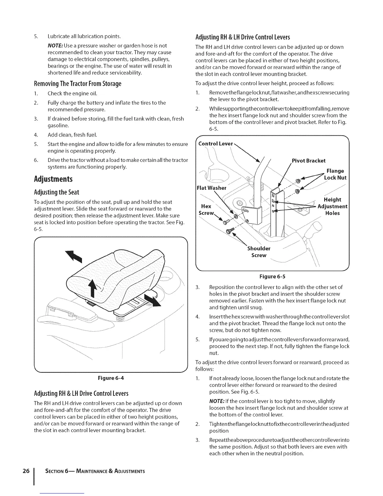
To adjust the drive control lever height, proceed as follows:
2.
_ontrol
Removetheflangelocknut,flatwasher, and hexscrewsecuring
the lever to the pivot bracket.
Whilesu pportingthecontrollevertokeepitfromfalling,remove
the hex insert flange lock nut and shoulder screw from the
bottom of the control lever and pivot bracket. Refer to Fig.
6-5.
Pivot Bracket
Flange
Flat Washer
Height
Adjustment
Holes
Shoulder
Screw
Figure 6-5
3. Reposition the control lever to align with the other set of
holes in the pivot bracket and insert the shoulder screw
removed earlier. Fasten with the hex insert flange lock nut
and tighten until snug.
4. Insertthe hex screwwith washerthrough the control leverslot
and the pivot bracket. Thread the flange lock nut onto the
screw, but do not tighten now.
5. Ifyouaregoingtoadjustthecontrolleversforward orrearwa rd,
proceed to the next step. If not, fully tighten the flange lock
nut.
To adjust the drive control levers forward or rearward, proceed as
follows:
If not already loose, loosen the flange lock nut and rotate the
control lever either forward or rearward to the desired
position. See Fig. 6-5.
NOTE: If the control lever is too tight to move, slightly
loosen the hex insert flange lock nut and shoulder screw at
the bottom of the control lever.
2. Tightentheflangelocknuttofixthecontrolleverintheadjusted
position
3. Repeatthea boveproced uretoadjusttheothercontrolleverinto
the same position. Adjust so that both levers are even with
each other when in the neutral position.
SECTION 6-- MAINTENANCE & ADJUSTMENTS
 Loading...