R-Series Models RP and RH Temposonics
®
Linear-Position Sensors - SSI Output
Product Data Sheet, Part No.: 550989 Revision E (EN) 05/2014 MTS Sensors10
R-Series Model RH Rod-Style Sensor
Mounting and Cylinder Installation
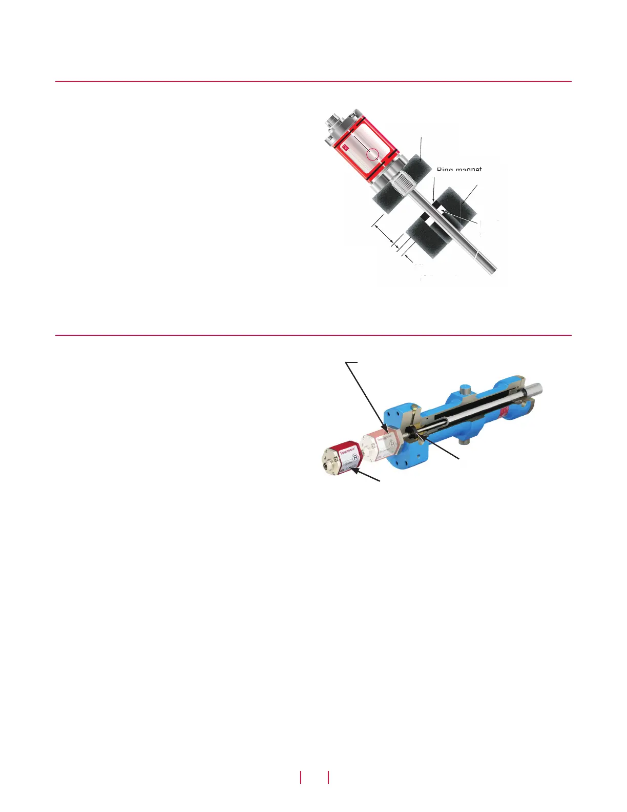
Model RH rod-style sensor mounting
MODEL RH SENSOR MOUNTING
The position magnet requires minimum distances away from ferrous
metals to allow proper sensor output. The minimum distance from
the front of the magnet to the cylinder end cap is 15 mm (0.6 in.).
The minimum distance from the back of the magnet to the piston
head is 3.2 mm (0.125 in.). However, a minimum distance of at
least 5 mm (0.197 in.) is preferred for added performance margin.
The non-ferrous spacer (part no. 400633), provides this minimum
distance when used along with the standard ring magnet (part no.:
201542-2) as shown in Figure 13.
Cylinder installation
The sensor’s rod housing and flange can remain
permanently installed in the cylinder
Ring magnet
The sensor cartridge, consisting of the electronics housing
and sensing element, is easy to replace by removing
(2) M4 thread 2.5 mm hex socket head screws
Figure 14. Fluid cylinder installation
Figure 13.
Non ferrous
spacer
> 15 mm
(0.6 in.)
Min. 3.2 mm
(0.125 in.)
Ring magnet
Cylinder end cap
Piston head
Temposonics
®
R-Series
R
®
Model RH rod-style mounting
When used for direct-stroke measurement in fluid cylinders, the
sensor's high pressure, stainless steel rod installs into a bore in
the piston head/rod assembly as shown in Figure 14. This method
guarantees a long-life and trouble-free operation.
The sensor cartridge can be removed from the flange and rod hous-
ing while still installed in the cylinder. This procedure allows quick
and easy sensor cartridge replacement, without the loss of hydraulic
pressure.

 Loading...


