R-Series Models RP and RH Temposonics
®
Linear-Position Sensors - SSI Output
Product Data Sheet, Part No.: 550989 E (EN) 05/2014
MTS Sensors
3
R-Series SSI Sensor Output Options and
Measuring Modes
Synchronous Serial Interface (SSI)
Temposonics R-Series sensors with SSI fulfill all requirements of the
SSI standard for an absolute encoder. The position value is encoded
in a 24/25/26 code format and is transmitted at high speed in SSI
standard format to the control device. The main feature of SSI is the
synchronized data transfer. Data transfer synchronization simplifies
the closed-loop control system.
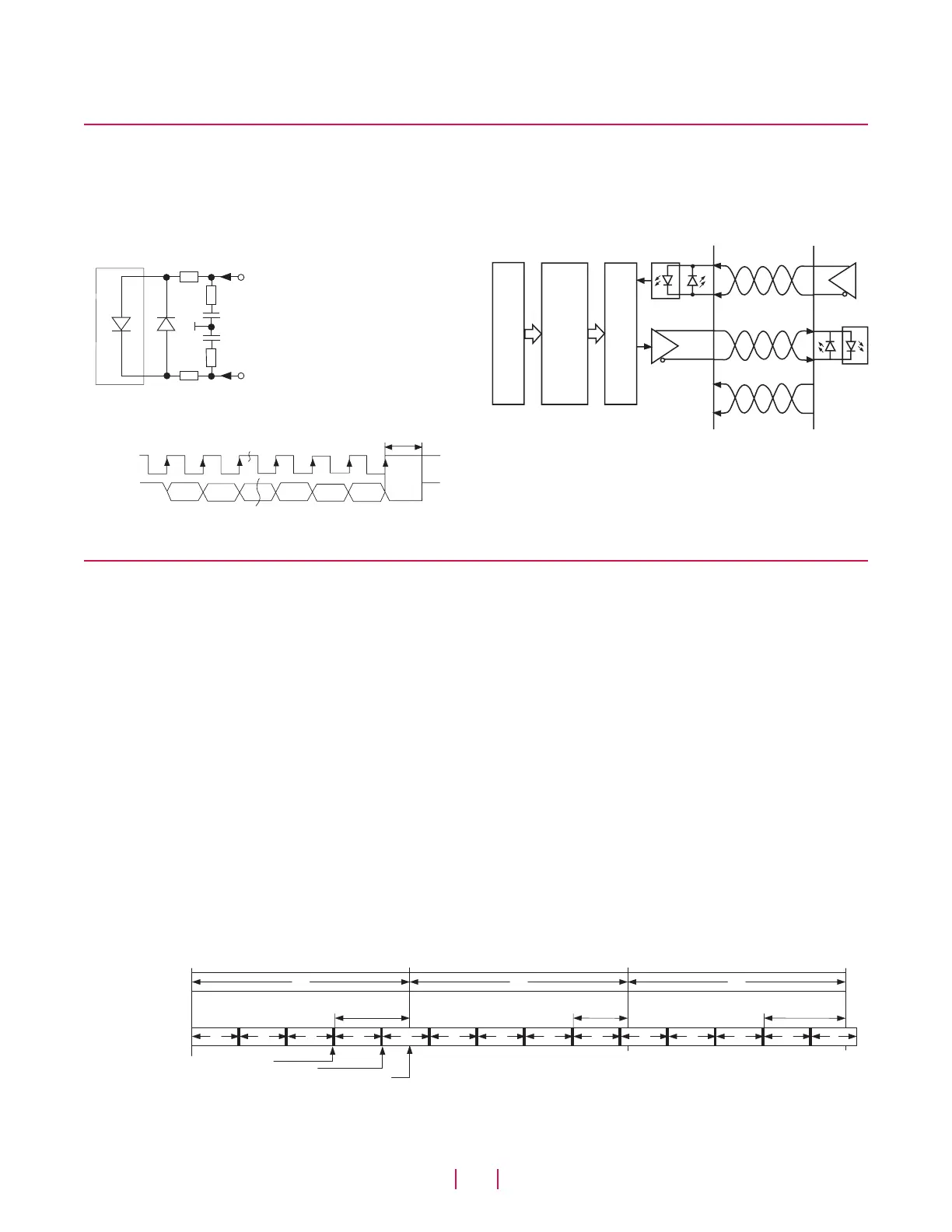
A clock pulse train from a controller is used to gate out sensor data.
One bit of position data is transmitted to the controller for each clock
pulse received by the sensor (see ‘Figures 1 and 2’). The absolute
position data is continually updated by the sensor and converted by
the shift register into serial information. (see ‘Figure 3’).
Figure 1.
Optocoupler
91 ohms
7 mA
Clock (+)
100 ohms
LED
2 Vdc
1 nF
Clock (-)
91 ohms
100 ohms
Sensor input
Figure 2.
Clock (+)
Data (+)
LSB
MSB
Timing Diagram
Figure 3.
Clock (+)
Clock (-)
Data (+)
Data (-)
+24 Vdc
0 Vdc
Driver
Optocoupler
ASIC for absolute position data
Microprocessor system
position value = 24/25/26 bit
Binary or Gray code
Shift register
Parallel serial converter
Logic Diagram
Measuring modes
THE SENSOR MEASUREMENT CYCLE
For all Temposonics position sensors, the measurement cycle begins with a very short electrical current pulse being applied to the sensor’s
waveguide. This is called the 'interrogation pulse'. It creates a magnetic field that interacts with another magnetic field emanating from the
position magnet. This interaction produces the magnetostrictive effect and results in a localized mechanical strain in the sensor’s waveguide.
When the interrogation pulse ends, the strain is suddenly released, sending a rotational sonic strain pulse down the waveguide. The measure-
ment cycle ends when the sonic strain pulse arrives at the end of the waveguide and is detected by the sensor’s electronics. By accurately
measuring the travel time of the sonic strain pulse the magnet’s precise position is determined.
ASYNCHRONOUS MEASURING MODE
For the SSI sensor, the position data is always communicated to the controller or PLC using the Synchronous Serial Interface format. When
the SSI sensor is operated as fast as possible, i.e. in Asynchronous Measuring Mode, the position data is updated and stored inside the sensor
as quickly as the sensor’s measurement cycle will allow. The minimum time for the measurement cycle is determined by the sensor’s overall
stroke length.
The controller’s loop time will determine when the sensor’s stored data is collected. For this mode the controller loop time is not synchronized
with the sensor’s measurement cycle time. However, if it is always slower than the sensor’s cycle time then there will always be new position
data available in the sensor’s shift register, waiting to be clocked out over the SSI interface.
As shown in ‘Figure 4 ’, although the sensor is updating the position data as fast as possible, the actual data values collected by the controller
can have varying delay times. This is shown as the delays from when the magnet’s position was captured, (at the instant the interrogation pulse
had started the relevant measurement cycle), to when the data is delivered at the end of the controller loop cycle.
Figure 4.
Controller
loop timing
Sensor
measurement cycle
Measurement starts
Data available
Data delivered
Delay
T
c
T
c
T
c
Delay
Delay
T
s
T
s
T
s
T
s
T
s
T
s
T
s
T
s
T
s
T
s
T
s
T
s
T
s
T
s
Asynchronous measuring mode, controller loop timing

 Loading...


