Introduction
MTS Landmark™ Tabletop Load Units - Product Information 39
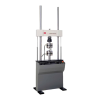
Item Component Description
4 Crosshead Moves up and down the column to accommodate different
sized specimens and fixtures. The crosshead is stiff and light
weight; it is one end of the force train.
5 Crosshead lifts Raise and lower the crosshead hydraulically to accommodate
different specimen sizes. The lifts are small hydraulic
actuators.
6 Force transducer Measures the forces applied to specimen. It is a strain gage
type, accurate in both dynamic and static tests. Both axial and
axial-torsional force transducers are available.
7 Isolation pads Dampen the load unit’s natural frequency to about 20 Hz.
8 Accumulators Store hydraulic fluid under pressure to increase the actuator’s
response time. One accumulator connects to the pressure
line; the other to the return line.
9 Servovalve Controls both the amount and the direction of fluid entering
the actuator using a high response valve. It determines how
fast the actuator can move in a linear direction.
10 Manifold Serves as the junction point between the hydraulic power unit
(HPU), accumulators, servovalve, and actuator. The manifold
is mounted to the crosshead. It is also a hydraulic circuit that
connects the hydraulic components.
11 Hydraulic crosshead
locks
Lock the crosshead to the frame for testing. They can be
unlocked to move the crosshead to other positions.
12 Linear actuator Applies axial forces to specimens. The actuator is a
hydraulically powered device that provides linear
displacement of (or forces into) a specimen. Grips and
fixtures can be mounted to the actuator.