MUELLER
®
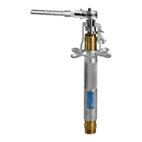
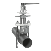
DH-5 / EH-5 Drilling Machines
Operating Instructions
4
8. Open valve being used.
9.
drill contacts the pipe to be drilled.
10.
amount.
11.
that the yoke is engaged with the
top of the friction collar on boring
mechanism on side of yoke so that it
is positioned under friction collar and
lock in place with operating screw.
Close bleeder located at bottom of
the machine before drilling operation
is begun.
12. Measure and mark the travel
required to complete the drilling
operation. (Mark the point on the
body that the feed tube will reach
when drilling is completed.)
13. DRILL MAIN – POWER
OPERATED METHOD USING
H-604 AIR OR H-704 HYDRAULIC
POWERED OPERATOR.
The DH-5 and EH-5 Drilling
Machines have been designed
to permit the addition of a power
operator. The power operator will
drive the tools and provide automatic
feed during the drilling operation.
IMPORTANT: When using H-604
air motor power operator,
maintain pressure of 90psi. We
recommend the use of a gage
at the throttle to determine the
actual pressure of air at the motor.
1. Oil all working parts, especially
the collar on the boring bar. Keep
oil treated surfaces and boring bar
well lubricated and free from dirt and
foreign material. (Invert the DH-5
or EH-5 Machine and lubricate it
through both lower and top oil holes
in addition to the points mentioned
previously.)
DH-5 and EH-5 Machines are
equipped with O-ring packing.
Under normal conditions the only
maintenance required for these
O-rings is lubrication. If the O-rings
should become excessively worn
they should be replaced.
NOTE: Avoid using petroleum-
based lubricants.
2.
tools may be attached.
3.
bar. If drilling tools to be used
will not pass completely through
the machine adapter to be used,
attach the machine adapter before
attaching the drilling tools (see
instruction no. 5).
4.
®
cutting grease to the leading edges
of the shell cutter and/or drill.
5.
adapter to the body of the machine
making sure that the body gasket
or washer is in place and in good
condition.
6.
position.
7.
machine adapter to the valve that is
to be drilled through.
The gear case attaches to the
machine by the means of two
sockets. The inner or small socket
drives the boring bar. The outer
or large socket drives the feed
yoke through a gear reduction
as the boring bar is rotated. The
revolution of the boring bar.
The operator takes the torque
of the motor resulting from the
drilling operation, so the motors
are equipped with a squeeze-type
trigger throttle. If for any reason a
drill should stick, the motor can be
shut off quickly.
a) Place the gear case and motor on
the drilling machine aligning the
sockets with the square shank
on the boring bar and feed yoke.
should be closed and wing nut
tightened securely.
clockwise rotation of boring bar.
5
operation
 Loading...