Composite Piping Layout and Design
Understanding the function and friction loss of each part of the piping system is important to
the layout and successful installation of a chilled liquid solution system.
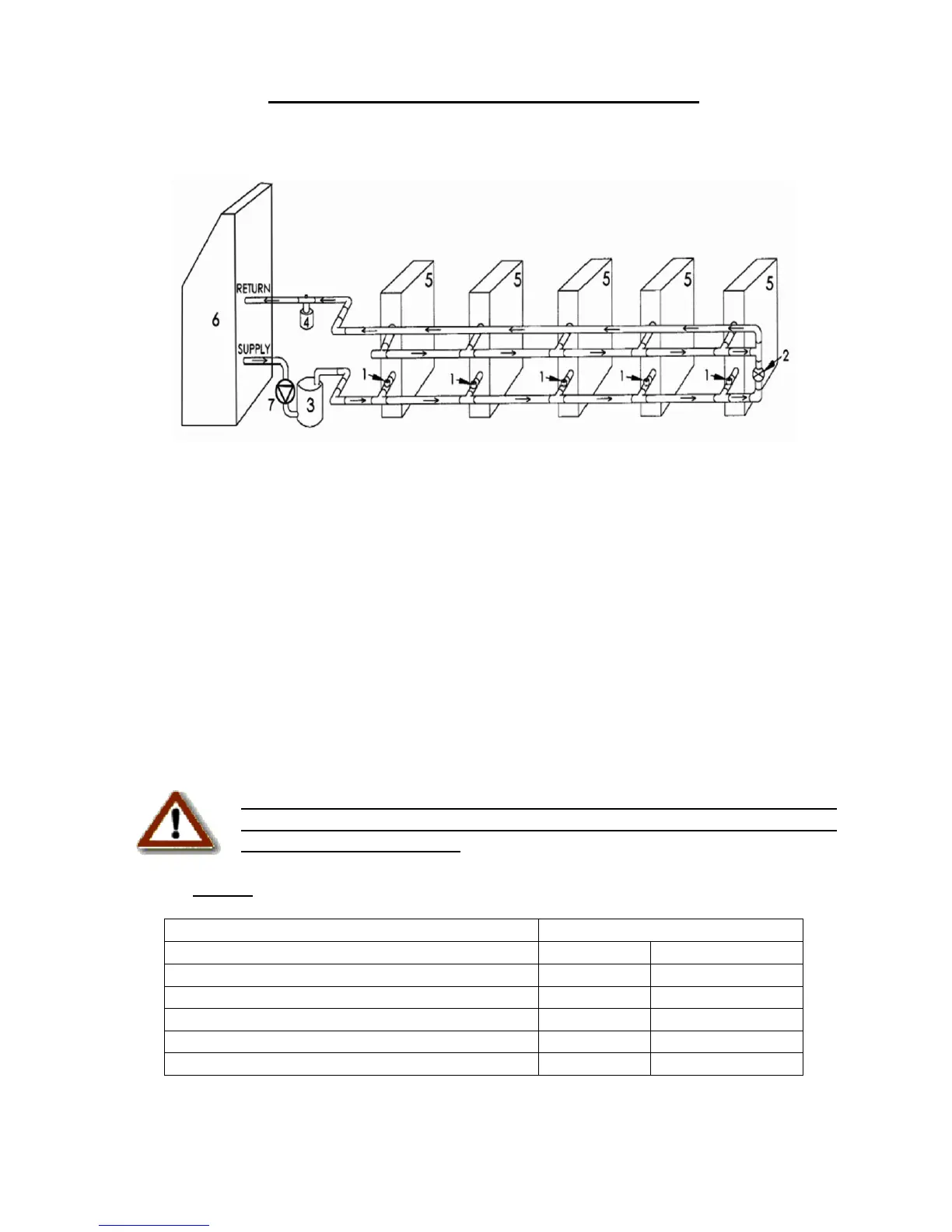
1– 2 Way Liquid Solution Control Valve
2– Bypass Valve
3– Storage Tank
4– Expansion Tank
5– Fan Coil Unit
6– Chiller
7– Pump
The circulation pump is the key performer in the piping system. The pump must circulate the
liquid solution through the heat exchanger and piping system to the air handlers. Pumps are
designed to deliver a flow rate measured in gallons per minute (GPM). The pump must be
able to overcome the resistance to flow (pressure drop) imposed by the chiller components,
piping system, and air handlers while maintaining the necessary flow rates in gallons per
minute. Pump capacities in gallons per minute and pressure drop (feet of head) are listed in
Table 1.
An adjustable valve or balancing valve must be used to throttle the
discharge liquid solution flow rate to appropriate levels based on capacity
and glycol mix percentages.
Table 1 Chiller System Data
Min. Liquid Solution Flow Rate
Max. Liquid Solution Flow Rate
Min. Total Liquid Solution Content of System
Internal Chiller Pressure Loss
Chiller Liquid Solution Content
Piping resistance or pressure drop is measured in feet of head. A foot of head is the amount of
pressure drop imposed in lifting liquid solution one foot.
Page 13 of 28