sensor temperature reaches 130°C
the
main relay trips shutting down
the
motor.
The relay cannot be reset until
the
RTD temperature falls below the trip value.
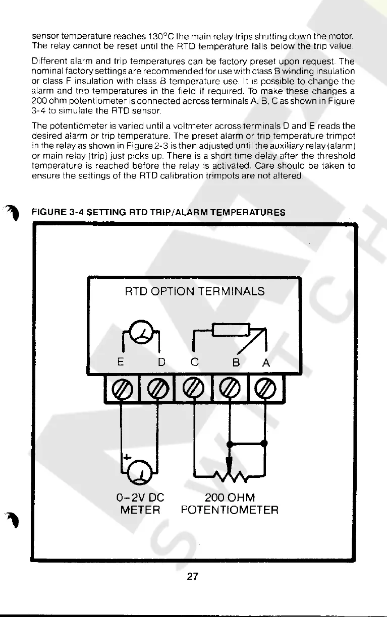
Different alarm and trip temperatures can be factory preset upon
request
The
nominal factory settings are
recommended
for use with class 8 winding insulation
or class F insulation with class B temperature use. It
is
possible
to
change the
alarm and trip temperatures in the field
if
required.
To
make these changes a
200 ohm potentiometer
is
connected across terminals
A,
B,
C
as
shown
in
Figure
3-4
to simulate
the
RTO
sensor
The potentiometer
is
varied until a
voltmeter
across terminals 0 and E reads
the
desired alarm
or
trip temperature. The preset alarm
or
trip temperature trimpot
in the relay
as
shown in
Figure2-3
is
then adjusted until
the
auxiliary relay {alarm)
or main relay (trip) just picks up. There
is
a short time delay after the threshold
temperature
is
reached before
the
relay
is
activated. Care should be taken to
ensure the settings of the RTD calibration trimpots are not altered .
• " FIGURE
3-4
SETTING RTD
TRIP/ALARM
TEMPERATURES
RTD OPTION TERMINALS
E
D
0-2V
DC
METER
c
B
A
2000HM
POTENTIOMETER
27
Courtesy of NationalSwitchgear.com
 Loading...
