Do you have a question about the Multimetrix CM603 and is the answer not in the manual?
Operator must read and understand precautions, be aware of electrical hazards, and use the instrument as specified.
Lists items included in the product packaging: batteries, leads, thermocouple, manual, and carrying case.
Step-by-step guide for inserting batteries using a screwdriver to access the compartment cover.
Explains that 'OL' on the display indicates a measured quantity outside the current range.
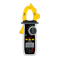
Describes the hand-held CM603 clamp multimeter's ease of use for measuring various electrical parameters.
Instructions for connecting leads and setting the switch for DC or AC voltage measurements.
Procedure for measuring frequency or duty cycle using the Hz% key after setting voltage range.
Guide to using the clamp jaws to measure AC current, centering the conductor.
Steps for measuring resistance, diode forward voltage, and continuity using the SLT key.
Process for measuring capacitance, including power cut-off and lead placement.
Instructions for connecting a K thermocouple and setting the switch to measure temperature.
Details on the automatic shut-off feature to save batteries and how to suppress it.
Specifies reference values for temperature, humidity, supply voltage, frequency, and signal type.
Details voltage, frequency, duty cycle, current, and resistance measurement ranges and uncertainties.
Defines operating and storage temperature/humidity ranges, pollution degree, and altitude limits.
States the instrument is powered by three 1.5V alkaline batteries (AAA or LR3).
Provides dimensions, clamping diameter, mass, and drop test rating for the instrument.
Lists safety standards (IEC, UL, CSA) and measurement category (CAT III) compliance.
Specifies EMC standards for emission and immunity in industrial environments.
Guidance on cleaning the instrument with a damp cloth, avoiding solvents, and keeping air gaps clean.
Instructions for replacing batteries when the low battery symbol appears, and proper disposal.
Outlines the warranty period and conditions under which it is voided.
| Continuity Test | Yes |
|---|---|
| Diode Test | Yes |
| Display Type | LCD |
| Safety Rating | CAT III 600V |
| AC Voltage Range | 600V |
| DC Voltage Range | 600V |
| Measurement Functions | AC/DC Current, AC/DC Voltage, Resistance, Continuity, Diode |
| Voltage Range AC | 600V |
| Voltage Range DC | 600V |
| Power Supply | 2 x AAA batteries |