lI
you
now
lold
the aileron up and down a number of times,
the
two strips of tape will bond in the
centre, to
produce
a
perfect
tape hinge. The basic requirement for this form
of
hinge is
that
the trailing edge ot the wing and the leading edge of the aileron
were left with a straight,
sharp edge, as described
in
the building
instructions.
Connect the threaded
pushrod
to the aileron horn and check
the aileron movement. Apply
a small blob oI s-minute epoxy to
the end ot the
pushrod
to secure it. Repeat the
procedure
with
the second aileron and
the elevator.
Installing the radio
control equipment
The
guide
tubes already in
place
in the fuselage usually have to
be shortened in the cabin area. They
can be cut through with a
sharo
knile.
Install the servos in the Iuselage. Fit
the clevises 39 about half-
way
onto the threaded
portion
of the threaded
couplers 38, and
connect the links to
the servo outout discs.
Set the control surfaces and servos to neutral,
and the airbrakes
to
fully
closed.
Mark
the correct length
of the
linkage
rods
for
the
control surfaces
(the
shoulder ol the threaded
coupler) us-
ing a telt
-tip
pen,
cut the rods to length and
de
-
burr the cut
enos.
Roughen up the steel rods,
bend the ends into a
gentle
"S"
shape, and solder them into
the threaded couplers.
Check that the bowden cables are as
straight as
possible,
and
give
them extra support
by
gluing
them to the fuselage side at
several
points
with epoxy.
Glue
pieces
oI scrap wood
(the
re-
mainder of
strip
47)
under the ends of the bowden
cable outers.
Check
that the
control surface neutral
oositions
and throws are
correct, and check that all systems work freely.
Check also that
the
control"sense"
is
correct, i.e. moving the rudder
stick
to the
right results in the rudder moving
to lhe right. The airbrake and
aileron
linkages
are completed in the
same
manner. Here
again,
check
control surface
movements
and sense.
Check that all control surfaces, and in
particular
the airbrakes,
are able to move
to the servos' extremes of travel without being
mechanically obstructed
at any
point.
A stalled servo consumes
a very high
current, and thus depletes the receiver battery in
a
very short time.
Fit the receiver battery into
the
fuselage
nose and
pack
round it
with foam rubber. The receiver
battery should h ave a capacity of
at least
1200
mAh. Hook
-
and
-
loop
tape
(Velcro)
is ideally
suit-
ed to fixing batteries.
The receiver is fixed to the luselage
side using the same
mate-
rial.
The receiver aerial
can be deployed inside the fuselage by slip-
ping
it inside a length
of
plastic
tubing
(bowden
cable outer),
which is left loose in
the
fuselage.
The aerialtube is not included
in the kit. On no account
use
metal
tubing!
Mount
the On/Off
switch on the servo
plate
13 inside the fuselage. The
canopy
is
taken off to
switch
the radio
on or off.
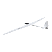
Tuöulators
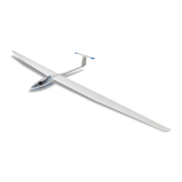
The wings of the DG 600
can
be fitted with
optional turbulators.
lf
you
wish to fit them, cut two narrow, 2 mm wide
strips
lrom
the
tape 57, using a steel straight edge and a sharp knite. They
should be 300
mm long.
These strips are stuck down on the
plug
-
in wing
extensions,
running from
the tip inboard,
parallel
to the leading
edge,
and
about
25mm
apart. Cut through the
tape at the
wing
-
extension
joint
line.
The effect of the turbulators is
to
improve
control and handling
characteristics atthe lowend ofthe
speed
range,
just
as
they do
on the
tull-size
aircraft.
For
slow
flight
in thermals they
promote
accurate, elegant circling, and the turbulators
prevent
asymme-
trical stalling
(tipstalling)
i.e. the model
stalls
gently,
straight
ahead.
The
turbulators convert the
laminar
airflow to a turbulent flow,
which is able to tollow the airfoilsection lor much longerwithout
breaking up; this can lead to considerable loss in
performance
at slow flight speeds.
Balancing
Your DG 600 must be
balanced at the
marked
Centre of Gravity
before
you
attempt a flight. Minor inaccuracies in
construction,
which are unavoidable in modelling, may result in the
CG
posi-
tion shown
not
being exactly correct; even a very small differ-
20
ence
in wing
sweep
angle will affect the
CG
position
noticeably.
Forthis reason the model is initially balanced at an average CG
position,
which will in
all cases
be
good
enough
for test flights.
The ideal
CG
position
can
then be established toryour
particu-
lar
model
during test-flying. This average CG
forthe
DG 600
is
at the
wing
joiner
blade
position.
I/ark the
CG
on the underside of the wing roots using a felt
-tip
pen.
Fit out the model completely, including radio equipment,
canopy
and
tail surlaces.
The model can simply be
balanced
on
your
fingertips; this is
quite
accurate enough for the initial average
CG
position.
Add
lead
ballast to the
fuselage
nose untilthe model balances with
the nose inclined
slightly downward.
You will need
between
1
00
and 300
grams
of lead, depending
on
your
methods
ol cons-
truction and finishing and the type of radio installed.
Secure
the
ballast with foam rubber
or
Velcro
taoe.
Test-flying
The model is now ready to be launched by winch from a
ground
take
-ofl.
Forthe firstflightwe recommend fitting the
plug-in
ex-
tensions. Switch the receiving system on and carry out a check
oI all controls. Check once more that the control surfaces move
in the
correct
direction
corresponding to stick
movement. When
you
are satistied, connect the winch line.
It is best if an
assistant
holds
the
model
steady, concentrating
on keeping the wings level. Give the signalto release the model
as soon as there
is
sufficient tension on the
line.
lmmediately after leaving the
ground
the model is in the n
,
dangerous
phase
of tne
iaunci. tf
tne
model is
allowed to cliffb
away sleeply
lrom
the
ground,
a stall
is very likely.
The
model
will
drop one
wing
and can only be recovered by applying oppo-
site
rudder
at once.
To
avoid this,
never
pull
the
model
up stee-
ply
immediately after lift
-
off,
but wait a few moments
until
it has
achieved
llying
speed, even applying a little down
-elevator
if
necessary.
Once the
model is in
a stable condition, the climb
can be continued; apply slight up-elevator to maximise launch
height.
The winch operator should watch the degree of flex in the wings
during the
whole
of the
winch launch,
as this
indicates
the
load
on the model, and tells him whethertoapply moreorless
power.
In blustery weather a winch launch
places
considerable loads
on a model, loads which are exceeded only during aerobatic fly-
ing.
After releasing the tow, trim the model tor accurate straight
tlight, with
the
Iuselage
pointing
in
exactly the same direction
as
the
direction ol
flight
-
either
into wind
or
downwind. This is of
great
importance if
you
wish to obtain maximum
performance
from
your
model.
An aircraft which is constantly
yawing
can
never
gives
its best
performance,
owing to increased
Iuselage
drag and the angled airflow over the wings. Adjust the trans,-'!
ter trims
until
true
"hands
ofi"
fliqht is achieved.
J
Now tly a few full circles, if
possible
in both directions, and ob-
serve
how
the control surlaces
respond. lt is worth
saying
here
that all
pilots
develop their own ideas on how to tly an aircraft,
and
we
can only
give general
advice.
It
you
tind one
control
ope-
rates too
sharply or
too
sluggishly, eliminate
the
problem
at
once hy
reconnecting
the
linkage
at
the
servo output
arm. lt
makes no
sense
at all to fly a model for a long time with unba-
lanced control responses. Equally, do not alter the settings
once
you
have established a
good
combination.
It
takes a certain amount of time
to
get
the best
performance
out
of any
good
sailplane with the controls set up in a
particularway,
let
alone
when
you
constantly
make
changes.
lf
you
still have enough height, check the CG
position
right on
your
first
test
flight.
However, do
not
attempt
it if
you
are
getting
low. lt is much
better
in that
case
to land and carry out the test
during a second
llight.
The
simplest
and
quickest
method of checking the CG is to in-
vestigate the
model's
recovery
lrom
an
intentional
dive.
This
characteristic
is a function of the interaction between Centre of
Lift and Centre of Gravity at different speeds.
We must
point
out,
however, that this method represents a fine-tuning
procedure,
and
it will lail
completely
il
you
have made
gross
errors
in
cons-
truction, or it the average CG
position
shown has not been ad-
hered to.
Place
the model in a dive by holding in down-elevator
for
a
few
moments. Release the stick. lf the model is balanced correctly,
it will recover from the dive by itself in a broad,
gentle
curve.
lf
 Loading...