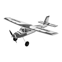
Congratulations on your new FunCub XL!
Y
ou will need the following tools to build the model:
• 2 x Zacki Elapor
# 85 2727
• Hot-glue gun
• Cross-point screwdrivers, large and small
• Balsa knife
• Pointed-nose pliers
• Allen key, 1.5 mm A/F
• 6 mm A/F open-ended spanner
• 10 mm A/F open-ended spanner
• 13 mm A/F open-ended spanner
•
Additional items required if you intend to install the POWER-MUL-
TIlight:
• 2 M6 plug # 8 5213
• 2 M6 sockets # 8 5214
• Soldering iron
• Solder
Before starting construction:
Please check that the kit contents are complete by comparing
the parts supplied with the Parts List on page 31 Figs. 01 & 02
1. Preparing the fuselage shells, installing the servos (KIT)
Locate the pre-assembled M-Frame 30 and glue it in the right-hand
fuselage shell 5 using Zacki. Now glue the M-Frame " oats support
31, the two clip hinges “A” 71, the Canopy Lock clip 73 and the
aero-tow coupling 75 in the appropriate positions.
Figs. 03 + 04
Glue the second Canopy Lock clip 73 in the left-hand fuselage
shell 4 in the same way.
Centre the elevator servo (HiTec HS-225BB # 11 2225) from your
transmitter, then fi x the output lever on the servo output shaft.
The lever should point left when the inscription on the servo label
is the right way up (legible). Fit the retaining screw. Connect the
servo to the 600 mm extension lead (# 8 5032), and apply a little
adhesive tape around the connectors to prevent the plug working
loose in fl ight. Fit the elevator servo in the opening in the right-
hand fuselage shell 5, with the cable facing forward, and secure
it with hot-melt glue at both mounting lugs.
Fig. 05
Install the rudder servo (HiTec HS-225BB # 11 2225) as described
for the elevator servo - but with the output lever facing in the op-
posite direction. Connect it to a 600 mm extension lead (# 8 5032)
and secure it with tape, then glue the servo in the opening in the
left-hand fuselage shell 4.
Fig. 06
2. Joining the fuselage shells, attaching the external parts
(KIT)
Before joining the fuselage shells 4 + 5 permanently, fi t them to-
gether “dry” (without glue), and check that everything fi ts correctly.
When you are satisfi ed, apply Zacki to the joint surfaces of one
fuselage shell, and glue the two mouldings together.
Figs. 07 + 08
Now glue the dummy air outlets 24 + 25, the upper cowl fairings
26 + 27 and the fuselage facing ribs “L” 76 and “R” 77 in the
positions shown.
Figs. 09 + 10
Invert (turn over) the fuselage and glue the “rear” exhaust fairing
29
to
the underside of the fuselage. Glue the cargo door supports
“A” 32 and “B” 33 in place, followed by the tailwheel support 56.
Figs. 11 + 12
3. Completing the cowl and canopy (KIT)
Take the moulded cowl 7 and glue the “front” exhaust fairing 28
to the underside using Zacki.
Figs. 13 + 14
The cowl is fi xed to the fuselage using magnets. Glue three of
the magnets 34 in the moulded-in recesses in the cowl 7, and
the remaining three to the recesses in the front of the fuselage.
!CAUTION!: it is important to fi t the magnets the right way
round,
i.e.
the pairs of magnets which come into contact with each
other
m
ust attract - not repel! Do not place the cowl on the fuselage unti
l
the glue has set hard!
Figs. 15 - 17
Now
glue the two Canopy Lock lugs 74 in the moulded slots in
the canopy 6 using Zacki.
Fig. 18
4. Installing the motor (KIT)
Screw the metal cruciform motor mount to the motor using the four
cross-head screws supplied. Apply a drop of thread-lock fl uid to
each screw, and tighten them fi rmly.
Fig. 19
Remove the cowl from the fuselage before installing the motor.
This is the procedure: place the plastic cruciform motor mount 131
between the metal cruciform mount (attached to the motor) and the
motor bulkhead (part of the M-Frame). Fix the motor assembly in
place using the four M3 x 12 mm retaining screws 132 and 3 mm
I.D. washers 133. The cowl can now be replaced on the fuselage.
Figs. 20 + 21
5. Installing the main undercarriage (KIT+RR)
First fi x the angle strut brackets 36 to the underside of the main
undercarriage unit 35 using two M3 x 6 mm cross-head screws 37
on each side. The fi rst main wheel 39 can now be attached to the
main undercarriage unit using the axle 40 (M6 x 45 mm machine
screw)
and one M6 self-locking nut 41 on each side. Ensure
that
the wheel is still free to rotate smoothly when you have tightened
the nuts. Repeat the procedure on the other side of the main
undercarriage.
Fig. 22
When the undercarriage is complete, fi x the assembly to the
M-Frame using four M3 x 20 mm retaining screws 42. Note that
the strut retaining brackets must be at the rear (towards the tail)!
Fig. 23
6. Installing the tailwheel unit (KIT+RR)
The fi rst step in assembling the tailwheel unit 47 is to slip the lower
bush 48
through
the hole from the underside. Fit the upper
bush
46 on top, and glue these parts together with a little Zacki. The
tailwheel spigot 49 can now be slipped through the bush from the
underside.
The spigot is secured with the steering lever 44: fi t
an
M3 x 6 mm cross-head screw 45 in the shaft driver 43 which fi ts
in
the steering lever 44. Ensure that the screw engages on
the
machined area of the spigot.
The
bottom end of the spigot is bored and threaded M3. Fit the
tailwheel yoke 50 on the spigot, engaging the square section in
the hole, and fi t an M3 x 10 mm cross-head screw 55 and a 3 mm
I.D. washer 54 to secure it. Tighten the screw fi rmly.
Now fi t the tailwheel 51 and tailwheel shaft 52 (M2 x 22 mm
)
between
the wheel and the tailwheel bracket, together with
two
M2.5 nuts 38 (as spacers), and secure the wheel with the M2
self-locking nut 53
.
Fig. 24