J36/B46-M30 SERIES WALK-BEHIND TROWELS • OPERATION MANUAL — REV. #1 (11/17/17) — PAGE 43
MAINTENANCE
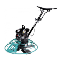
Trowel Arm Inspection
Trowel arms (Figure 65) can be damaged by rough handling
such as dropping the trowel, or by striking exposed
plumbing, rebar, or other objects while in operation. A
bent trowel arm will prevent smooth, fluid rotation of the
blades. If bent trowel arms are suspected, examine them
for straightness as shown below.
Figure 65. Trowel Arm
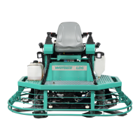
1. Place the trowel arm on a thick, steel plate, granite slab,
or any other surface which is true and flat (Figure 66).
Figure 66. Trowel Arm Inspection
2. Check each of the six sides of the trowel arm hex
section (Figure 66). A feeler gauge of .004 inch
(0.10 mm) should not pass between the flat of the
trowel arm and the test surface along its length on the
test surface.
3. As the flat hex section rests on the test surface, use
a feeler gauge of .005 inch (0.127 mm) to check the
clearance between the round shaft section and the test
surface. Rotate the arm to each of the flat hex sections
and check the clearance between the round shaft and
the test surface. The clearance between the round shaft
and the test surface should be identical for each hex
section. See Figure 66.
TROWEL ARM
ROUND SHAFT
SECTION
ROLL PIN
HOLE
BLADE ATTACHMENT
BOLT HOLE
FLAT OF
HEXAGONAL SHAFT
(TOP OF ARM)
LEVER
MOUNTING
SLOT
TROWEL ARM
HEXAGONAL (HEX)
SHAFT SECTION
SURFACE
HEX SECTION
FEELER GAUGE
ROUND SECTION
FEELER GAUGE
.005 IN./0.127 MM
4. Replace any bent or uneven trowel arms.
Trowel Arm Adjustment
The easiest and most consistent way to adjust a trowel arm
is with the trowel arm adjustment tool (P/N 1817).
Once locked into the adjustment tool, each trowel arm
bolt is adjusted until it contacts a stop on the fixture. This
will consistently adjust all of the trowel arms, keeping the
finisher as flat and evenly pitched as possible.
The trowel arm adjustment tool comes with usage
instructions and all the hardware necessary to correctly
perform this adjustment.
Perform the following procedure to adjust trowel arms using
the trowel arm adjustment tool.
1. Unscrew the locking bolts on the adjustment tool and
place a trowel arm (with lever attached) into the fixture
channel as shown in Figure 67.
Figure 67. Trowel Arm Adjustment
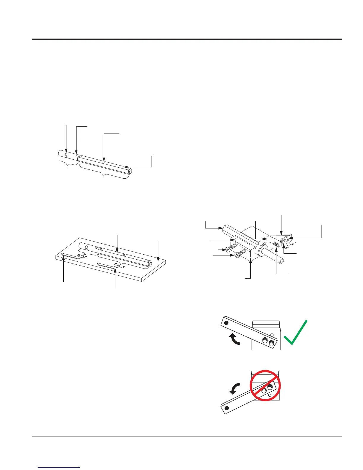
2. Make sure the fixture arm is in the UP position
(Figure 68).
Figure 68. Fixture Arm Position (UP)
TROWEL ARM
(PLACED IN
FIXTURE CHANNEL)
TROWEL
ARM
LEVER
FIXTURE
ADJUSTMENT
BOLT
FIXTURE
ARM
DISTANCE = .010 in.
TROWEL ARM
LOCKING
BOLTS
SHIM
TROWEL ARM
TROWEL ARM
ADJUSTMENT BOLT
.010"
UP
DOWN
CORRECT
INCORRECT
 Loading...