Do you have a question about the MULTIQUIP WHITEMAN MD105 and is the answer not in the manual?
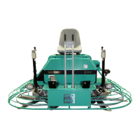
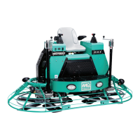
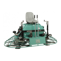
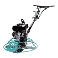
Identifies the specific model and type of equipment covered in the manual.
Explains the risks of crystalline silica inhalation and potential cancer risks.
Outlines general respiratory hazards from dust, mists, and fumes encountered during operation.
A checklist to guide training for new operators on equipment operation and safety.
A checklist for essential daily checks before operating the equipment.
Explains the meaning of DANGER, WARNING, CAUTION, and NOTICE safety messages.
Defines various safety symbols used in the manual and on the equipment.
Explains the meaning and function of various safety decals found on the equipment.
Lists essential safety measures such as protective gear and hazard avoidance.
Important notices regarding operation, maintenance, and emergency preparedness.
Warnings about carbon monoxide and need for engine airflow.
Safety for engine compartment, heat shields, hot oil, and exhaust parts.
Stay clear of moving parts; do not disable safety devices.
Engine run-time limits, air filter importance, and governor settings.
Precautions for flammable fuel, refueling, and storage.
Safety measures for battery handling, acid, and charging.
Safety guidelines for lifting, transporting, and tie-down procedures.
Rules for towing, fluid disposal, recycling, and decommissioning.
Details engine's design to reduce harmful emissions and EPA certification.
Warns against emission system mods and explains label importance.
Emphasizes sling inspection and warns of severe injury from sling failure.
Requires trained personnel and outlines critical lifting safety measures.
Lists conditions that mandate immediate removal of slings from service, such as damage or wear.
Ensures forklift capacity and specifies choker hitch method for slings.
Explains how choke angle affects sling strength and the need for de-rating.
Describes using forklift pockets for lifting the trowel.
Provides instructions for securing the trowel using tie-down straps and symbols.
Final step on securing the trowel to a flatbed with tie-down straps to prevent movement.
Lists detailed technical specs for the trowel and its engines.
Presents data on sound pressure, sound power, and whole body vibration levels.
Lists the length, width, and height of the trowel with corresponding measurements.
Defines designated purpose, safety rules, and operator training.
Describes engines, blades, hydraulic system, and diagnostic display.
Locates spray controls, grab bars, seat switch, and pitch controls.
Identifies retardant tank, hydraulic coolers, and hydraulic motors.
Describes spider assemblies with blades and the dual Honda engines.
Details foot pedal, retardant spray systems, and LED lights.
Explains the diagnostic display and engine fault indicators.
Covers hydraulic oil reservoir check and the Machine Control Unit.
Describes power module, hydraulic pumps, filter, and stabilizer rings.
Details steering controls, lift loops, cup holders, and carbon canisters.
Covers fuel tank capacity, ignition switch, and service port.
Identifies fuel filter, oil cooler, oil filler port, dipstick, and drain bolts.
Explains air cleaner function and spark plug specifications, exhaust manifold.
Covers cooling fan, regulator rectifier, ECU, and starter.
Advises battery safety and tilting seat for access.
Instructions for securing battery and connecting cables correctly.
Step-by-step guide to checking and adding engine oil.
Procedure for visually inspecting and topping up hydraulic oil.
Warnings about hot hydraulic oil and proper refill procedures.
Alerts about fuel flammability and refueling steps.
Warns that fuel spillage on a hot engine can cause fire or explosion.
Emphasizes reading operation section, wearing protection, and avoiding confined areas.
Explains the seat switch preventing blade rotation without an operator.
Guides on mounting the trowel and using the ignition switch.
Describes display status for key switch ON, engine idle, and active faults.
Daily procedure to verify the operational status of the safety seat switch.
Strong warning against disabling the seat switch due to safety risks.
Explains how operator presence affects throttle and idle speed.
Illustrates joystick movements and their results on trowel direction.
Explains how the foot pedal controls engine and rotor speed.
Guides on moving the trowel forward and backward using joysticks and foot pedal.
Encourages practicing maneuvers, pitch, spray, and lights.
Instructions on how to use cruise control and its safety interlocks.
Instructions for adjusting blade pitch using Twin Pitch™ and Left Pitch switches.
Steps for safely shutting down the engines and cleaning the trowel.
Explains float pan function and safety rules for installation.
Instructions for routing and securing the latch pin to lock the float pan.
Lists engine maintenance tasks like oil, filters, spark plugs, and valve clearance checks.
Lists trowel maintenance tasks like lubricating arms and inspecting wiring.
Notes items to be serviced by a dealer and frequent cleaning needs.
Warns that some maintenance requires specialized knowledge and skill.
Step-by-step guide for cleaning foam and paper filter elements.
Details cleaning methods for paper and foam filters, with warnings.
Warns against running the engine without an air cleaner to prevent damage.
Instructions for checking engine oil levels and adding oil if necessary.
Detailed steps for performing an engine oil change, including torque specs.
Instructions for inspecting, gap checking, and replacing spark plugs.
Specifies torque for installing new or used spark plugs.
Cautions about loose or overtightened spark plugs causing engine damage.
Specifies intervals for changing the hydraulic oil filter.
Procedure for draining hydraulic oil from the reservoir, with hot oil warning.
Guidelines for battery terminal checks, storage, and charging warnings.
Table outlining lubrication points, shots, and intervals for trowel maintenance.
Daily lubrication for spider assemblies, including fitting locations and steps.
Daily lubrication for thrust collars, including fitting locations and steps.
Step-by-step guide for replacing trowel blades, emphasizing consistency.
Explains how to adjust blade pitch for consistent finishing quality.
Lists signs for adjustment and mentions the special adjustment tool.
Procedure for checking and ensuring proper spider assembly alignment using test areas.
Detailed steps for removing spider assembly and safety precautions with catch chains.
Identifies key parts of the rotor assembly like spider hub and cap plug.
Details removing hex head screws securing trowel blades.
Lists torque values for socket-head screws during reassembly.
Step-by-step instructions for removing trowel arms from the spider hub.
Guides on examining, cleaning, and replacing bronze trowel arm bushings.
Instructions for reinstalling bronze bushings and trowel arms.
Procedure for inspecting trowel arms for bends or unevenness using feeler gauges.
Describes using the trowel arm adjustment tool for consistent adjustment.
Details positioning the fixture arm and setting the adjustment bolt distance.
Step-by-step guide for adjusting trowel arms using the adjustment tool.
Procedure for replacing spider assembly socket-head bolts, including intervals.
Steps for reassembling the spider assembly and lubricating grease points.
Safety warnings for bolt removal and instructions for cleaning bolt holes.
Details installing new bolts with thread sealant and specified torque.
Continues bolt installation and re-torquing steps for spider assemblies.
Procedure for safely retiring and disposing of unserviceable equipment, including fluid and battery disposal.
Steps to prepare the trowel for long-term storage, including battery and fuel removal.
Describes how faults are indicated by horn, LEDs, and Check Engine icon.
Instructions on viewing fault codes and correcting identified problems.
A table listing diagnostic display fault codes and their descriptions.
Explains the amber LEDs indicating engine faults and their flashing patterns.
A table listing engine indicator fault codes, flashes, and possible causes.
Possible problems and solutions if the seat switch fails.
Troubleshooting steps for trowel bouncing, rolling concrete, or uneven swirls.
Checks blade condition, angle consistency, and pitch for rolling issues.
Steps to diagnose and resolve issues with the trowel's lights.
Diagnoses and resolves problems with the retardant spray system.
Diagnoses and resolves issues with unresponsive steering.
Diagnoses and resolves issues with the blade pitch system.
Addresses issues when the engine has fuel but no spark, checking plugs and ignition.
Addresses issues when fuel/spark present but engine won't start, checking ignition and fuel system.
Addresses issues with low compression, checking valves, pistons, and gaskets.
Labels electrical components visible from the front view of the trowel.
Labels electrical components visible from the top view of the trowel.
Diagrams showing layout of fuses and relays in front and rear boxes.
Tables mapping references to devices, parts, and quantities.
Illustrates wiring from fuse box and harnesses to the trowel's lights.
Illustrates wiring connections for the retardant spray switches and pumps.
Illustrates wiring for pitch switches and actuators.
Illustrates wiring for the seat switch safety system and its connections.
Illustrates wiring for the horn and cruise control system.
Strong warning against disabling the horn due to potential damage.
Illustrates wiring for hydraulic coolers and temperature switches.
Illustrates wiring connections for the hydraulic motors.
Illustrates wiring connections for hydraulic pumps and pressure sensors.
Illustrates the wiring connections for the foot pedal.
Illustrates wiring for the diagnostic display and engine indicators.
Shows connections related to the right engine harness.
Illustrates wiring related to the left engine harness and CAN resistors.
Shows primary power connections from the battery to the bus bar.
Details power connections to the right and left engine harnesses.
Illustrates wiring for the key switch and seat switch circuits.
Shows wiring for pitch actuators, foot pedal, and steering controls.
Depicts battery, ignition, and seat switch circuit wiring.
Illustrates wiring for hydraulic coolers, motors, pumps, and engine indicators.
Details wiring for hydraulic pumps, motors, and temperature switches.
Shows wiring for spray switches, cruise control, and ignition switch.
Depicts wiring for diagnostic display and engine indicators.
Provides detailed wiring for actuators, foot pedal, and related components.
Wiring for hydraulic motors, pumps, and spray systems.
Explains the symbols and wire types used in the schematic.
Specific wiring diagrams for hydraulic pumps and motors.
Wiring for spray pumps and worklights.
Wiring related to hydraulic pump and motor control signals and sensors.
Details wiring for hydraulic pumps, engines, and start/fault signals.
Identifies the location of various hydraulic components on the trowel.
Details specs for hydraulic cylinders, steering valves, and temp switches.
Describes hydraulic pumps, motors, coolers, and their operating parameters.
Legend explaining hydraulic lines and reservoir capacity.
Lists phone numbers, emails, and websites for customer support.
Contains copyright information, trademark acknowledgments, and disclaimers.