MD105 RIDE-ON TROWEL • OPERATION MANUAL — REV. #0 (03/29/24) — PAGE 41
SPIDER ALIGNMENT
A clean, level area to test the trowel prior to and after
trowel arm adjustment is essential. Any uneven spots in
the oor or debris under the trowel will give an incorrect
perception of alignment. A 3/4-inch-thick, at steel plate is
ideal for testing.
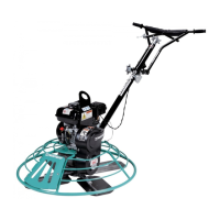
1. Place the trowel in a clean, level test area.
2. Pitch the blades as at as possible. The adjustment
bolts should all barely make contact with the lower
wear plate on the spider. Figure 40 illustrates the
correct alignment for a spider assembly as shipped
from the factory.
Figure 40. Correct Spider Alignment
3. If any adjustment bolts are not making contact with
the lower wear plate, adjustment will be necessary.
Figure 41 illustrates incorrect alignment, worn spider
bushings, or bent trowel arms.
Figure 41. Incorrect Spider Alignment
SURFACE
FLAT
FLAT
CORRECT ALIGNMENT
NO
SURFACE
DISHED EFFECT ON
FINISHED CONCRETE
SPIDER REMOVAL
To fully remove a spider assembly from the hydraulic motor
shaft:
1. Disconnect the negative (BLACK) battery cable from
the negative (–) terminal on the battery.
2. Lift the trowel as shown in the Lifting and Transporting
section.
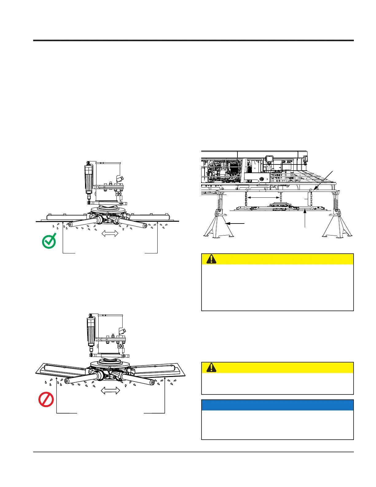
3. Place the trowel on heavy-duty jack stands
(Figure 42) on secure, level ground in an area that is
free of dirt and debris.
Figure 42. Preparation For Spider Removal
4. Attach one end of three equally spaced straps or catch
chains to the stabilizer ring (Figure 42). Attach the
other end of these straps or chains to the bottom
guard ring in a manner that would prevent the spider
assembly from falling.
CATCH
CHAINS
3–4"
SLACK
STABILIZER
RING
ATTACH CHAINS
TO BOTTOM
JACK
STAND
CAUTION
The bolt removal process may result in the sudden
separation of the spider assembly from the hydraulic
motor shaft. The use of catch chains is recommended
to prevent the spider assembly from falling and striking
personnel, causing bodily harm.
CAUTION
DO NOT use the intermediate guard rings to support
the spider assembly.
NOTICE
Make sure the catch chains are positioned so that they
are equally spaced, with no more than 3 to 4 inches
of slack.
MAINTENANCE
 Loading...