PAGE 4 — MD105 RIDE-ON TROWEL • OPERATION MANUAL — REV. #0 (03/29/24)
TABLE OF CONTENTS
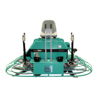
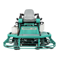
MD105 Ride-On Trowel
Proposition 65 Warning ........................................... 2
Silicosis/Respiratory Warnings ................................ 3
Table of Contents ..................................................... 4
Checklists ................................................................ 5
Safety Information ............................................. 6–12
Lifting and Transporting ................................... 13–17
Specications ........................................................ 18
Dimensions ............................................................ 19
General Information ............................................... 20
Components (Trowel) ...................................... 21–23
Components (Engine) ............................................ 24
Setup ..................................................................... 25
Inspection ........................................................ 26–27
Operation ......................................................... 28–33
Maintenance .................................................... 34–47
Troubleshooting ............................................... 48–52
Electrical Component Locator ............................... 53
Fuse and Relay Locator ........................................ 54
Lights Wiring Diagram ........................................... 55
Spray Wiring Diagram ........................................... 56
Pitch Wiring Diagram ............................................. 57
Seat Switch Wiring Diagram .................................. 58
Horn/Cruise Control Wiring Diagram ..................... 59
Hydraulic Coolers Wiring Diagram ........................ 60
Hydraulic Motors Wiring Diagram .......................... 61
Hydraulic Pumps Wiring Diagram .......................... 62
Foot Pedal Wiring Diagram ................................... 63
Display and Indicators Wiring Diagram ........... 64–65
Power and Ignition Wiring Diagram ................. 66–67
Electrical Schematic ........................................ 68–73
Hydraulic Component Locator ............................... 74
Hydraulic System Diagram .................................... 75
NOTICE
Specications are subject to change without notice.