MD105 RIDE-ON TROWEL • OPERATION MANUAL — REV. #0 (03/29/24) — PAGE 23
COMPONENTS
(
TROWEL
)
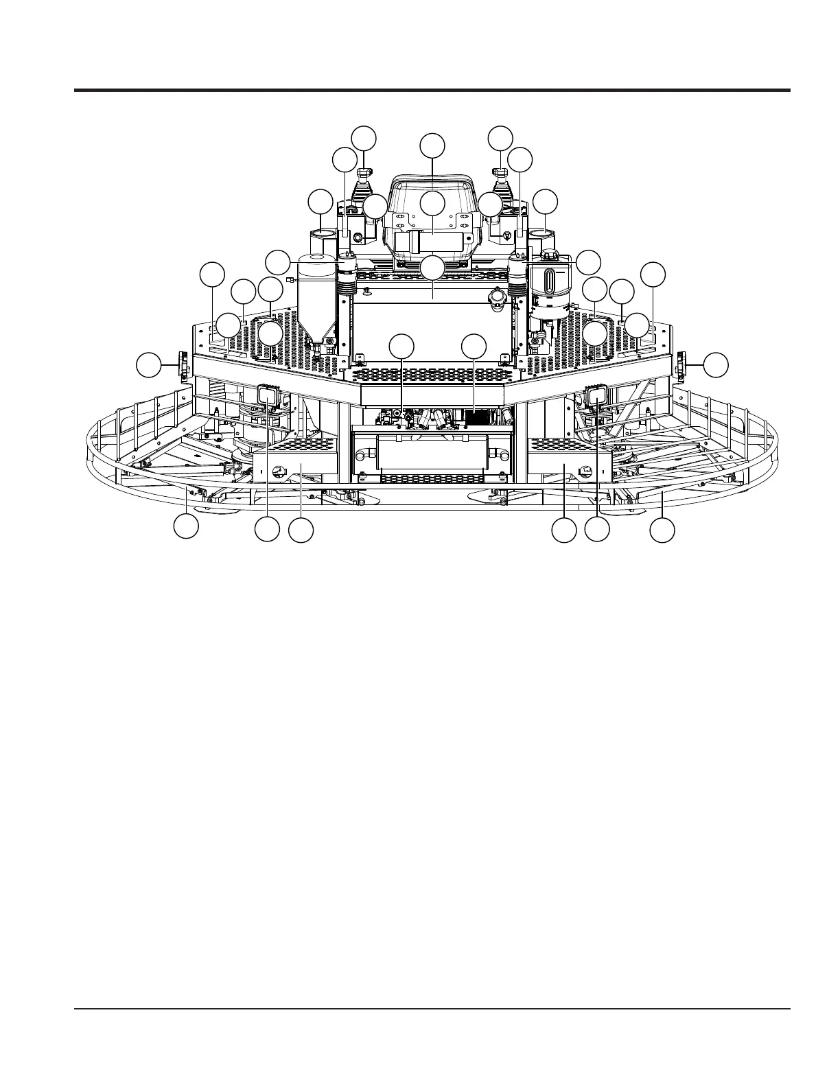
Figure 11. Trowel Components (Cont.)
27
28
29
30
3131
3232
3333
37
3434
16
35
35
35
35
35
35
35
35
35
35
36
36
16
16
16
12
11
24
12
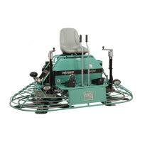
23. Power Distribution Module — Contains machine
fuses and relays.
24. Hydraulic Pumps (2) — Variable displacement,
axial-piston pumps drive the hydraulic motors that
turn the blades.
25. Trowel Platform — Spacious platform provides easy
access to the operator’s seat and service areas.
26. Hydraulic Filter — Filters hydraulic uid as it enters
the system. Equipped with 10-micron glass-lled lter
media.
27. Operator’s Seat — Adjustable operator’s seat tilts
forward for service access.
28. Document Holder — Storage for trowel and engine
manuals.
29. Fuel Tank — Holds 20 gallons (75.7 liters) of gasoline.
Remove the fuel ller cap to add gasoline to the fuel
tank. Use 86 octane or higher unleaded gasoline only.
30. Ignition Switch — Insert the ignition key here and turn
clockwise to start the engines.
31. Steering Control Handles (2) — Located to the left
and right of the operator, these dual palm-grip joysticks
are linked to three hydraulic steering cylinders. Refer
to the Operation section to learn more about steering.
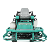
32. Lift Loops (2) — Attach lifting slings here to lift the
trowel. Refer to the Lifting and Transporting section
for more information.
33. Cup Holders (2) — Stainless steel cup holders.
34. Carbon Canisters (2) — Two containers lled with
activated charcoal reduce emissions and increase fuel
efciency by trapping gasoline vapor emitted by the
fuel system and releasing it to the engines.
35. Tie-Down Locations (10) — Secure tie-down straps to
these attachment points when transporting the trowel.
36. Stabilizer Rings (2) — Sectional design provides
enhanced stability and facilitates maintenance.
37. Service Port — Connect the Whiteman Service Tool
(WST) here to install and update trowel software and
perform adjustments and calibrations.



 To Next Page