PAGE 22 — MD105 RIDE-ON TROWEL • OPERATION MANUAL — REV. #0 (03/29/24)
COMPONENTS
(
TROWEL
)
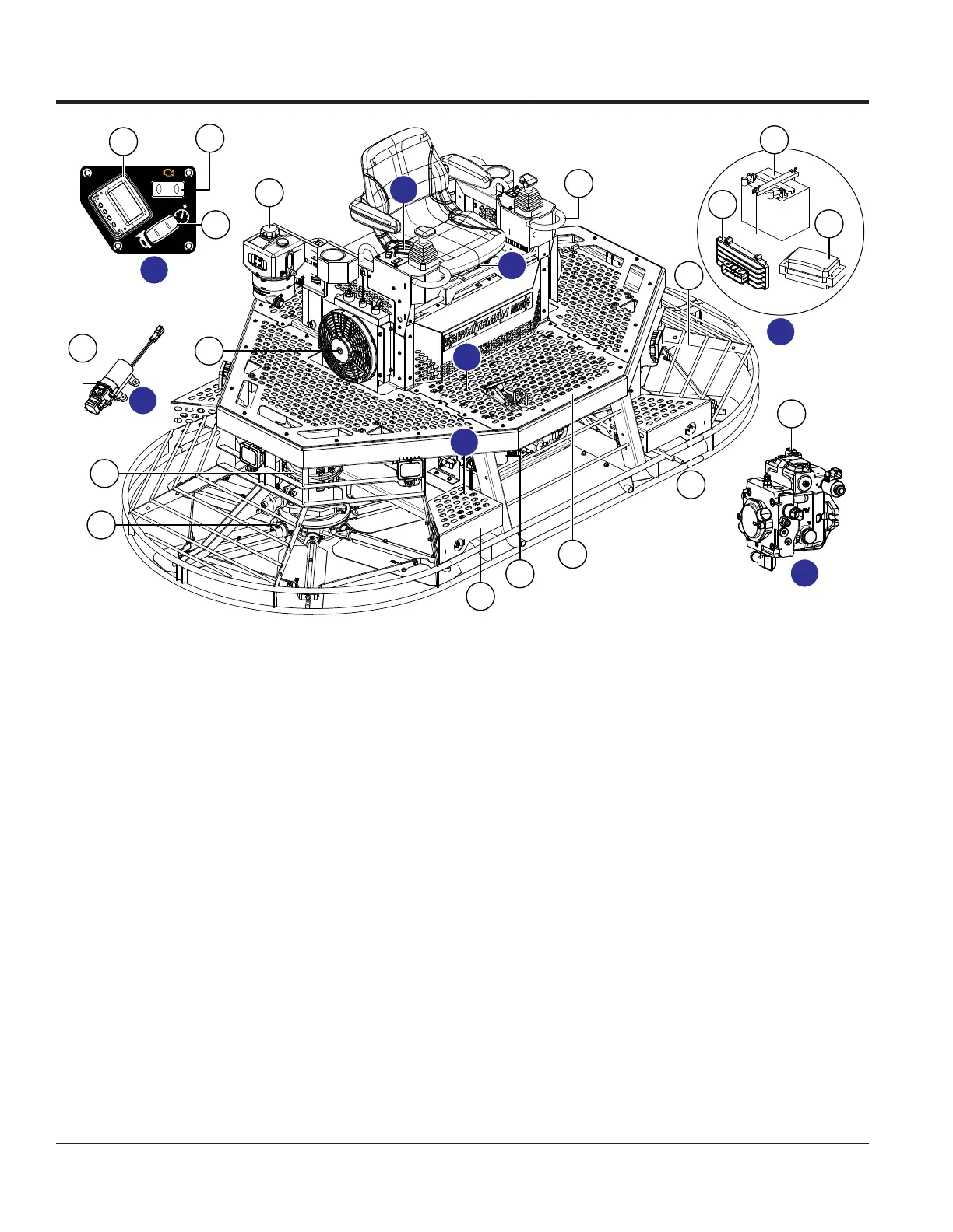
Figure 10. Trowel Components (Cont.)
1 2
17
18
19
20
2
21
22
23
16
15
14
25
12
10
9
8
26
D
D
E
E
F
G
G
F
24
12. Steps (4) — Use the steps to mount and dismount
the trowel.
13. Foot Pedal — Controls rotor speed. Slightly depress
the foot pedal to obtain minimal rotor speed. Fully
depress the foot pedal to obtain maximum rotor speed.
14. Retardant Spray Pumps (2) — Actuated by the
buttons on the steering control handles, these pumps
control the ow of retardant spray from the retardant
tank to the spray nozzles.
15. Retardant Spray Nozzles (2) — Actuated by the
buttons on the steering control handles, the spray
nozzles provide uniform coverage of retardant over
the slab surface.
16. Lights (6) — 20-watt LED lights provide illumination
for indoor or nighttime nishing.
17. Diagnostic Display — 2.3-inch LCD color display
provides trowel information at a glance. Refer to the
Diagnostic Display, Operation, and Troubleshooting
sections for more information.
18. Engine Fault Indicators — Indicator 1 lights when a
front engine fault exists, and Indicator 2 lights when
a rear engine fault exists. See the Troubleshooting
section for more information.
19. Horn/Cruise Control Rocker Switch — Use
this switch to activate the horn (beep beep) or to
activate/deactivate cruise control.
20. Hydraulic Oil Reservoir — Visually inspect the level
of hydraulic oil in the reservoir through the window
at the rear of the reservoir. Remove the ller cap
to add hydraulic oil. Open only when the system is
cool. Reservoir holds up to 1.28 gallons (4.84 liters)
of hydraulic oil. Use Parker DuraClean ISO 46 or
equivalent hydraulic oil only.
21. Machine Control Unit (MCU) — Connects to machine
sensors, switches, actuators, fuse box, engine, and
display to control the machine.
22. Battery — Provides +12VDC to the electrical system.
Tilt the operator’s seat forward to access the battery.
 Loading...