MD105 RIDE-ON TROWEL • OPERATION MANUAL — REV. #0 (03/29/24) — PAGE 45
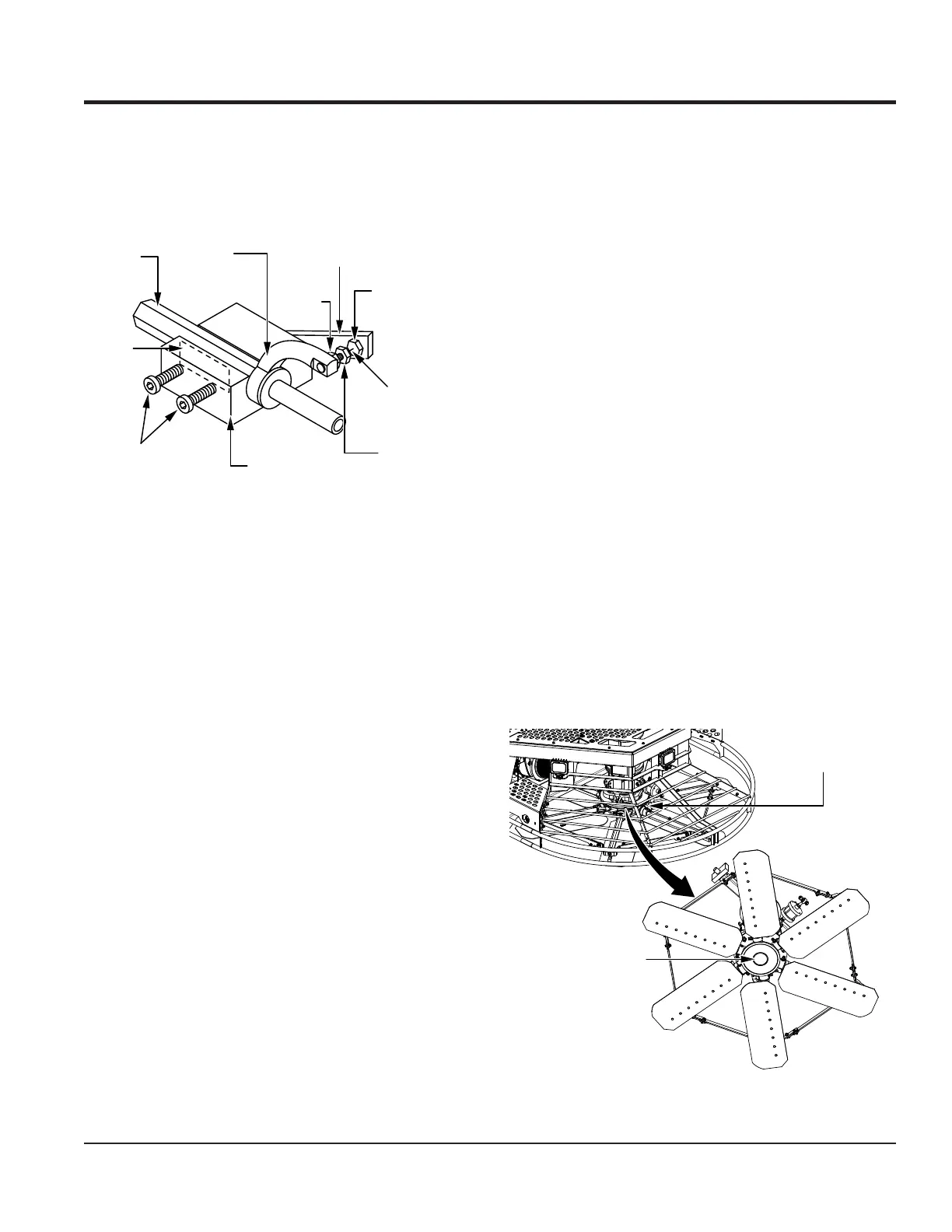
4. Unscrew the locking bolts on the adjustment tool and
place the trowel arm into the xture channel as shown in
Figure 51. A thin shim may be required to cover the blade
holes on the trowel arm. Make sure to align the trowel
arm adjustment bolt with the xture adjustment bolt.
Figure 51. Trowel Arm Adjustment
5. Tighten the locking bolts (Figure 51) with an Allen
wrench to secure the trowel arm in place.
6. Loosen the locking nut on the trowel arm lever
(Figure 51), then turn the trowel arm adjustment bolt
until it barely touches (0.010") the xture adjustment
bolt.
7. Once the adjustment has been made, tighten the
locking nut on the trowel arm lever to lock it in place.
8. Loosen the locking bolts and remove the trowel arm.
9. Repeat steps 2–8 for the remaining trowel arms.
10. Recalibrate pitch with the Whiteman Service Tool.
Reassembly
1. Clean and examine the entire spider assembly
including the upper and lower wear plates and thrust
collar. Wire brush any concrete or rust buildup. Replace
any spider components that are damaged or out-of-
round.
2. Make sure the bronze trowel arm bushings are
not damaged or out-of-round. Clean the bushings
if necessary. Replace any bronze bushing that is
damaged or worn.
3. Reinstall the bronze bushings onto the trowel arm.
ARM
TROWEL ARM
LEVER
ADJUSTMENT
BOLT
ADJUSTMENT
BOLT
LOCKING
NUT
0.010 in.
TROWEL ARM
ADJUSTMENT
TOOL
LOCKING
BOLTS
SHIM
FIXTURE
ARM
4. Repeat steps 2–3 for each trowel arm.
5. Make sure that the spring tensioner is in the correct
position to exert tension on the trowel arm.
6. Insert all trowel arms with levers (with bronze bushings
already installed) into the spider hub, using care to
align the grease holes on the bronze bushings with
the grease hole ttings on the spider hub.
7. Lock the trowel arms in place by tightening the hex
head bolts with Zerk grease ttings and jam nuts.
8. Reinstall the blades onto the trowel arms.
9. Reinstall the stabilizer struts onto the spider assembly.
10. Lubricate all grease points (Zerk ttings) with premium
Lithum 12-based grease, conforming to NLG1
Grade #2 consistency.
SPIDER BOLT REPLACEMENT
Existing bolts on both spider assemblies may self loosen
due to normal material yield. Replace the left- and right-side
spider assembly socket-head bolts (6 per side) and
hardened washers (1 per side) after the rst 25 hours of
operation, then every 100 hours of operation thereafter.
1. Perform steps 1–4 of the Spider Removal procedure.
2. Remove the left-side spider hub cap plug (Figure 52)
and set it aside.
Figure 52. Remove Left-Side Spider Hub Cap Plug
LEFT-SIDE
ROTOR ASSEMBLY
LEFT-SIDE
SPIDER HUB
CAP PLUG
(REMOVE)
BOTTOM
VIEW
MAINTENANCE
 Loading...