PAGE 44 — MD105 RIDE-ON TROWEL • OPERATION MANUAL — REV. #0 (03/29/24)
Checking Trowel Arm Straightness
Trowel arms can be damaged by rough handling such
as dropping the trowel on a pad or by striking exposed
plumbing, forms or rebar while in operation. A bent trowel
arm will prevent smooth, uid rotation of the blades. If bent
trowel arms are suspected, examine them for straightness
as follows:
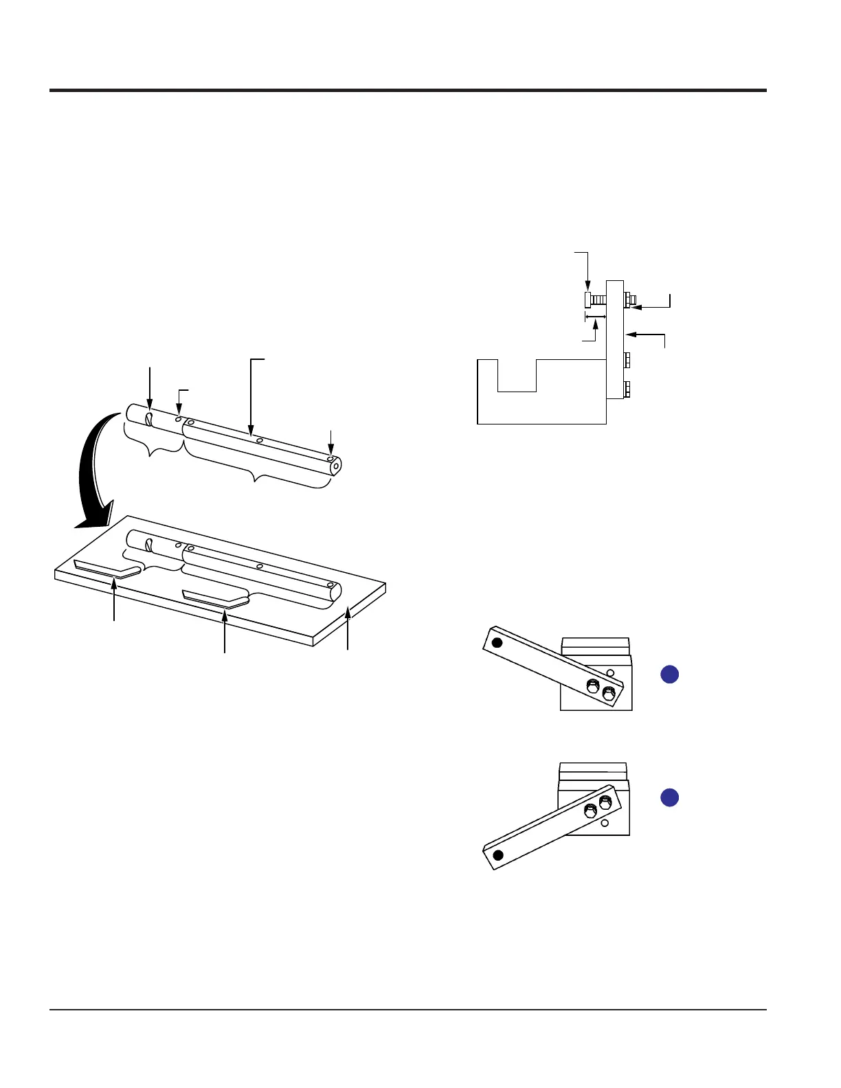
1. Place the trowel arm onto a thick steel plate, granite
slab, or any other surface which is flat and true
(Figure 48).
Figure 48. Checking Trowel Arm Straightness
2. Check each of the flat sides of the trowel arm
(Figure 48). A feeler gauge of 0.004 in. (0.10 mm)
should not pass between the at of the trowel arm and
the test surface along its length on the test surface.
3. Check the clearance between the short round shaft
section and the test surface as one of the at sections
of the arm rests on the test surface (Figure 48). Rotate
the arm to each of the at sections and check the
clearance of the round shaft. Use a feeler gauge of
0.005 in. (0.127 mm). Each section should have the
same clearance between the round of the trowel arm
shaft and the test surface.
4. Replace the trowel arm if it is bent or uneven.
FLAT TEST
SURFACE
FEELER GAUGE
(0.004 IN./0.10 MM)
FEELER GAUGE
LEVER
MOUNTING SLOT
(LEFT ARM SHOWN)
ROLL PIN
HOLE
BLADE
ATTACHMENT
BOLT HOLE
(1 OF 3)
FLAT OF
SHAFT
SHORT ROUND
SHAFT
SECTION
ROUND SHAFT
SECTION WITH FLATS
Trowel Arm Adjustment
Figure 49 illustrates a trowel arm adjustment tool. As a
trowel arm is locked into the adjustment tool, the trowel arm
bolt is adjusted to where it contacts a stop on the xture.
This will consistently adjust all of the trowel arms, keeping
the nisher as at and evenly pitched as possible.
Figure 49. Trowel Arm Adjustment Tool
(Side View)
1. Locate a trowel arm adjustment tool (P/N 9177).
2. Place the xture arm in the correct position (up or
down) for the trowel arm’s direction of rotation. For
trowel arms that rotate clockwise, place the xture
arm in the UP position (Figure 50A). For trowel arms
that rotate counterclockwise, place the xture arm in
the DOWN position (Figure 50B).
Figure 50. Fixture Arm Position
3. Adjust the xture adjustment bolt distance shown in
Figure 49 to 0.15 in. (3.81 mm).
ADJUSTMENT
BOLT
DISTANCE
LOCKING
NUT
FIXTURE
ARM
SIDE VIEW
B
A
MAINTENANCE
 Loading...