MD105 RIDE-ON TROWEL • OPERATION MANUAL — REV. #0 (03/29/24) — PAGE 49
TROUBLESHOOTING
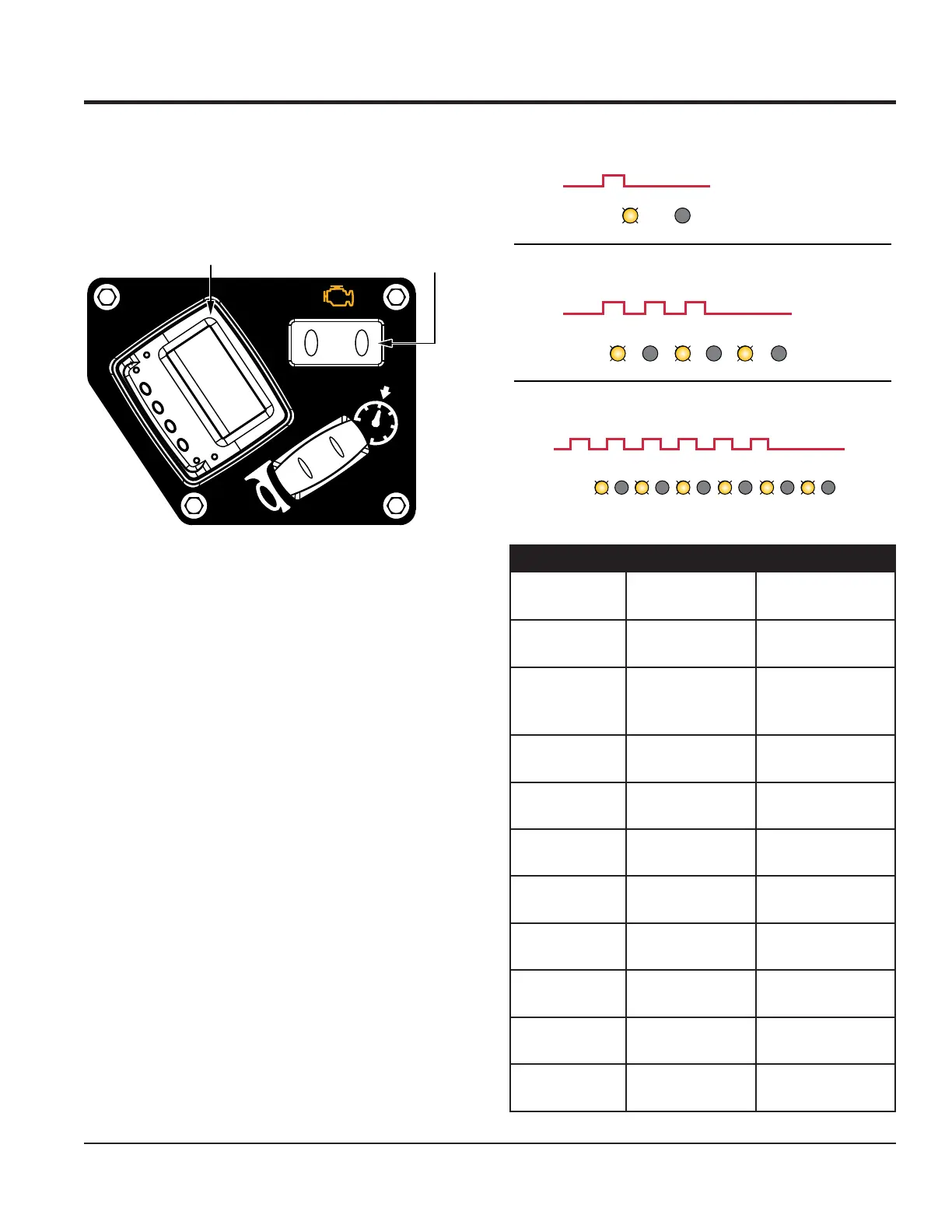
Engine Fault Indicators
In addition to the diagnostic display, the MD105 is
equipped with two amber LED lamps that serve as engine
fault indicators (Figure 59).
Figure 59. Right-Hand Control Panel
Engine fault indicator 1 (Figure 59) corresponds to the
front engine and engine indicator 2 corresponds to the
rear engine.
When an engine fault occurs, the corresponding engine
fault indicator will begin ashing in a pattern: the LED
will ash ON for 0.3 seconds, then OFF for 0.3 seconds
in a repeating sequence. The number of ON ashes in a
sequence determines the engine fault. There is an interval
of 1.5 seconds between each sequence.
See Figure 60 for illustrated examples of the ashing
patterns and Table 11 for a list of engine indicator fault
codes.
1 2
DIAGNOSTIC
DISPLAY
ENGINE FAULT
INDICATORS
Figure 60. Engine Indicator Flashing Patterns
FAULT 1 (ONE FLASH): ABNORMAL BATTERY VOLTAGE
ON: 0.3 SECONDS, OFF: 1.5 SECONDS (REPEAT)
TIMING:
(REPEAT)ILLUSTRATION:
ON 0.3S OFF 1.5S
FAULT 3 (THREE FLASHES): ABNORMAL TPS-1
ON: 0.3 SEC./OFF: 0.3 SEC. (2X), ON: 0.3 SEC./OFF: 1.5 SEC. (REPEAT)
TIMING:
(REPEAT)ILLUSTRATION:
ON 0.3S 0.3S
OFF 0.3S 0.3S
0.3S
1.5S
(REPEAT)
ON 0.3S 0.3S
0.3S
0.3S
OFF 0.3S 1.5S INTERVAL
FAULT 6 (SIX FLASHES): ABNORMAL TA SENSOR
ON: 0.3 SEC./OFF: 0.3 SEC. (5X), ON: 0.3 SEC./OFF: 1.5 SEC. (REPEAT)
TIMING:
(REPEAT)ILLUSTRATION:
ON 0.3S 0.3S 0.3S 0.3S 0.3S
OFF 0.3S 0.3S 0.3S 0.3S 0.3S
0.3S
1.5S
(REPEAT)
ON 0.3S
1.5S INTERVAL
ON 0.3S 0.3S
0.3S 0.3S 0.3S 0.3S
0.3S 0.3S 0.3S 0.3S
OFF 0.3S 1.5S INTERVAL
Table 11. Engine Indicator Fault Codes
Flashes per
Sequence
Fault Possible Cause
0: LED stays lit Oil alert
Harness or lack
of oil
1
Abnormal battery
voltage
Regulator/rectier
failure or over
electric load
2
Abnormal throttle
motor
Harness or throttle
valve stuck
3 Abnormal TPS-1
Harness or sensor
failure
4 Abnormal TPS-2
Harness or sensor
failure
5
Abnormal TPS
1 & 2 correlation
Harness or sensor
failure
6
Abnormal TA
sensor
Harness or sensor
failure
7
Abnormal TE
sensor
Harness or sensor
failure
8
Abnormal MAP
sensor
Harness or sensor
failure
9 Abnormal CPU
EEPROM or CAN
communication