MAYCO LS450 CONCRETE PUMP • OPERATION MANUAL — REV. #2 (02/23/21) — PAGE 25
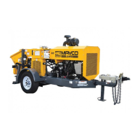
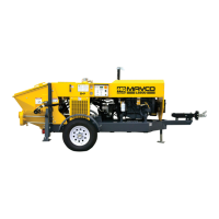
COMPONENTS (PUMP)
17. Hydraulic Oil Sight Glass — Use to determine the
amount of hydraulic oil remaining in the tank. The sight
glass also contains a temperature gauge for monitoring
the temperature of the hydraulic oil.
18. Control Box — Contains the electrical
components required to run the pump. See the
Components (Digital Control Panel) section for
component callouts.
19. Hydraulic Manifold Block — Manifold block
that controls the flow of hydraulic pressure to the
components required to control the pump.
20. Engine — Hatz Turbo Diesel 4H50 engine. See
Components (Engine) for more details.
21. Radiator — Fill only with recommended coolant.
Radiator coolant capacity is approx. 3.4 gallons
(13 liters).
22. Rear Running Lights — ALWAYS make sure both the
right and left running lights are functioning correctly
before towing the pump.
23. Hopper Discharge Sleeve — Connect hoses or steel
pipes to the discharge sleeve for pouring concrete.
24. Hydraulic Pump — This unit incorporates an axial
variable displacement hydraulic piston pump.
25. Volume Control — This device is electronically
controlled by the cylinder stroke switch located on
the front panel of the control box. The function of the
volume control is to set the pumping stroke.
26. Lubrication Box — This box is empty when shipped
from the factory. Please fill with 5.5 gallons (20.7 liters)
of SAE 30 motor oil for first-time use. Also check the
dual clean-out point on the bottom of the lubrication
box for a secure, tight fit.
27. Heat Exchanger — The function of the heat
exchanger is to cool the hydraulic oil when pumping
in high-temperature weather conditions. The exchanger
draws oil from the hydraulic tank through a filter and
into the heat exchanger before allowing it to flow into
the hydraulic system.
28. Accumulator — Stores hydraulic oil under pressure
and releases it to the shuttle cylinder. Provides the
pressure needed to ensure enough force is provided
during cycle.
29. Documentation Box — Contains engine and pump
operation, parts and maintenance information.
30. Remixer Motor — Drives the remixer paddles inside
the hopper. The motor direction is controlled by the
remixer control lever.
31. Hydraulic Stabilizer Control Lever (Right) — This
feature is an option. Push the lever downward to
extend the left hydraulic stabilizer. Push the control
lever upward to retract the stabilizer.
32. Hydraulic Stabilizer Control Lever (Center) — This
feature is an option. Push the lever downward to
extend the right hydraulic stabilizer. Push the control
lever upward to retract the stabilizer.
33. Remixer Control Lever — Controls the forward/reverse
motion of the hopper remixer paddles.
34. Hydraulic Stabilizer (Optional) — This feature is
an option. Heavy-duty left- and right-side hydraulic
stabilizers reinforce existing rear jack stands for
improved pump stability.