EasyManua.ls Logo

MULTISPAN PIC-4202 User Manual

MULTISPAN PIC-4202
4 pages
To Next Page IconTo Next Page
Page #1 background imageLoading...
Page #1 background image
All digit segment will be turned ON for 3 sec
Process Value
Set Value
1) Press Key to enter in parameter menu.
2) Press Key to go to next parameter.
4) Press Key to save change in setting
3) Use Or key to change value of parameter.
-999 To 9999 Selectable
2 Relay 1C/O
24V DC
Output
Transmitter
Supply
Power Supply
100 to 250V AC (SMPS)
Model
Display
Size
Panel Cutout
Input
Range
44 X 44
48 X 48 X 95
UPPER:- 4 Digit 7 seg .39”,red LED Display
LOWER:- 4 Digit 7 seg .28”,green LED Display
PIC-4202
0 To 10V DC,4 To 20mA DC,0 To 20mA DC
OPERATING MANUAL
PROCESS CONTROLLER
www.multispanindia.com
Page - 1
PIC-4202
PIC-4202
Technical Specification
Key Operations
PIC 4202


R1
R2

Other manuals for MULTISPAN PIC-4202

Question and Answer IconNeed help?

Do you have a question about the MULTISPAN PIC-4202 and is the answer not in the manual?

MULTISPAN PIC-4202 Specifications

General IconGeneral
Input TypeThermocouple, RTD, DC Voltage, DC Current
Control ModePID, ON/OFF, Manual
DisplayDual 4-digit LED
Input Channels2
Output Channels2
CommunicationRS-485 Modbus RTU
MountingPanel Mount
Output TypeRelay
Power Supply100-240 VAC 50/60 Hz

Summary

Technical Specification

Key Operations

Basic Key Functions

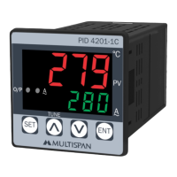
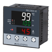
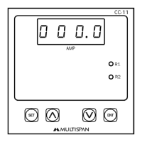
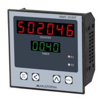
Describes how to navigate parameters and change values using SET, ▲, ▼, and ENT keys.

User Configuration

Set Point Configuration

Configures Set Point 1 and Set Point 2 values for process control.

Password and Hysteresis Settings

Sets user password and hysteresis values for set points 1 and 2.

Alarm Mode Selection

Selects alarm modes (Mode-1, Mode-2) for relay output behavior.

Input and Output Settings

Configures input type, decimal point, ranges, filter, and offset.

Configuration Parameters

Correction Factor and Signal Level

Sets correction factor and defines signal low level for input.

Working Principles

Operational Behavior and Indicators

Details device operation, display indications, and alarm behavior.

Connection Diagram

Related product manuals